
TB 9-4931-503-24
(26) Set oscilloscope calibrator EDGE output for 2.5 V, 1 kHz and adjust EDIT
FIELD knob for 5 divisions of vertical deflection on oscilloscope.
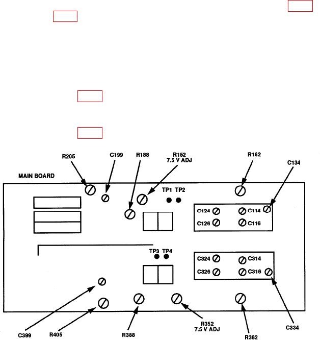
(27) If square wave level, roll off, or overshoot exceeds 4%, adjust C314 (fig. 4) for
flat top and C316 (fig. 4) for square corner on waveform.
(28) Release CH 1 GND pushbutton to out position. Remove 24 pF normalizer from
equipment setup and connect oscilloscope calibrator SOURCH/MEASURE CHAN 1 to TI
CH 2.
(29) Set TI CH 2 VOLTS/DIV switch to 2 m and oscilloscope calibrator VOLTAGE
output for 10 mV, 1 kHz. If necessary, adjust oscilloscope calibrator EDIT FIELD knob for
a 0.0% err display indication.
(30) Adjust R405 (fig. 4) for 5 divisions of vertical deflection on oscilloscope (R).
(31) Set TI CH 2 VOLTS/DIV switch to 10 m and oscilloscope calibrator VOLTAGE
output for 50 mV, 1 kHz.
(32) Adjust R388 (fig. 4) for 5 divisions of vertical deflection on oscilloscope (R).
Figure 4. Test instrument - left-side view.
22