
TB 9-4931-503-24
(3) MAIN VARIABLE CAL control fully cw to detent.
(4) AUTO TRIG pushbutton pressed.
(5) +SLOPE pushbutton pressed.
(6) DISPLAY MODE MAIN SWP pushbutton pressed.
(7) TRIG SOURCE RIGHT pushbutton pressed.
(8) All remaining pushbuttons released (out).
f. Adjust oscilloscope INTENSITY and FOCUS controls for suitable viewing.
19. Vertical Gain
a. Performance Check
(1) Connect oscilloscope calibrator SOURCE/MEASURE CHAN 1 to TI CH 1 input.
(2) Set TI CH 1 VOLT/DIV switch and oscilloscope calibrator VOLTAGE output,
at 1 kHz, as listed in first row of table 10.
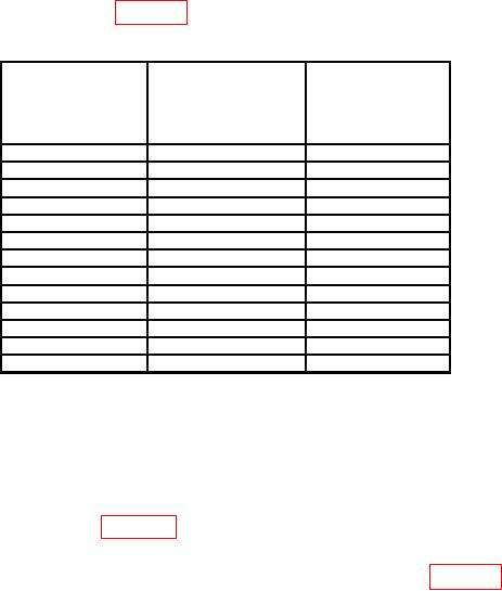
Table 10. CH 1 Vertical Gain
Oscilloscope
Oscilloscope
Test instrument
calibrator
calibrator
CH 1
err display
VOLTAGE output
VOLTS/DIV
indications
at 1 kHz settings
switch settings
( %)
1
mV
5
mV
5
2
mV
10
mV
5
5
mV
25
mV
3
10
mV
50
mV
3
20
mV
0.1
V
3
50
mV
0.25
V
3
0.1
V
0.5
V
3
0.2
V
1
V
3
0.5
V
2.5
V
3
1
V
5
V
3
2
V
10
V
3
5
V
25
V
3
10
V
50
V
3
NOTE
If necessary, adjust delaying time base controls for a stable
display.
(3) Adjust oscilloscope calibrator EDIT FIELD knob for 5 divisions of vertical
deflection on oscilloscope. If oscilloscope calibrator err display indication is not within
limits specified in first row of table 10, perform b (1) through (16) below. (No adjustment
can be made on TIs with main board (SN B056205 and below)).
(4) Repeat technique of (2) and (3) above for remaining rows in table 10.
(5) Move oscilloscope calibrator SOURCH/MEASURE CHAN 1 connection to TI
CH 2 input.