
TB 9-4931-503-24
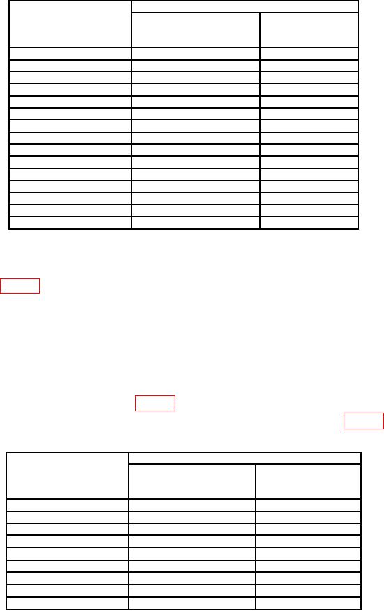
Table 8. Sweep Timing (Unmag) - Continued
Oscilloscope calibrator
Test instrument
err display
SECONDS/DIV
MARKER output
indications
switch settings
settings
( %)
0.1
ms
0.1
mS/D
3
0.2
ms
0.2
mS/D
3
0.5
ms
0.5
mS/D
3
1
ms
1
mS/D
3
2
ms
2
mS/D
3
5
ms
5
mS/D
3
10
ms
10
mS/D
3
20
ms
20
mS/D
3
50
ms
50
mS/D
3
0.1
s
0.1
S/D
3
0.2
s
0.2
S/D
3
0.5
s
0.5
S/D
3
1
s
1
S/D
3
2
s
2
S/D
4
5
s
5
S/D
4
(7) Press TI SWP MAG pushbutton.
(8) Set TI SECONDS/DIV switch and oscilloscope calibrator settings as listed in
first row of table 9.
NOTE
If necessary, adjust TI LEVEL control for a stable display.
(9) Adjust TI POSITION control to align 2d marker with 2d vertical graticule line
on oscilloscope.
(10) Adjust oscilloscope calibrator EDIT FIELD knob to align 10th marker with 10th
vertical graticule line on oscilloscope. If oscilloscope calibrator err display indication is not
within limits specified in first row of table 9, perform b below.
(11) Repeat technique of (8) through (10) above for remaining rows in table 9.
Table 9. Sweep Timing (Mag)
Oscilloscope calibrator
Test instrument
err display
SECONDS/DIV
MARKER output
indications
switch settings
settings
( %)
10
ns
10
nS/D
5
20
ns
20
nS/D
5
50
ns
50
nS/D
4
s
S/D
4
0.1
0.1
s
S/D
4
0.2
0.2
s
S/D
4
0.5
0.5
s
S/D
4
1
1
s
S/D
4
2
2
s
S/D
4
5
5
16