
TB 9-4931-530-50
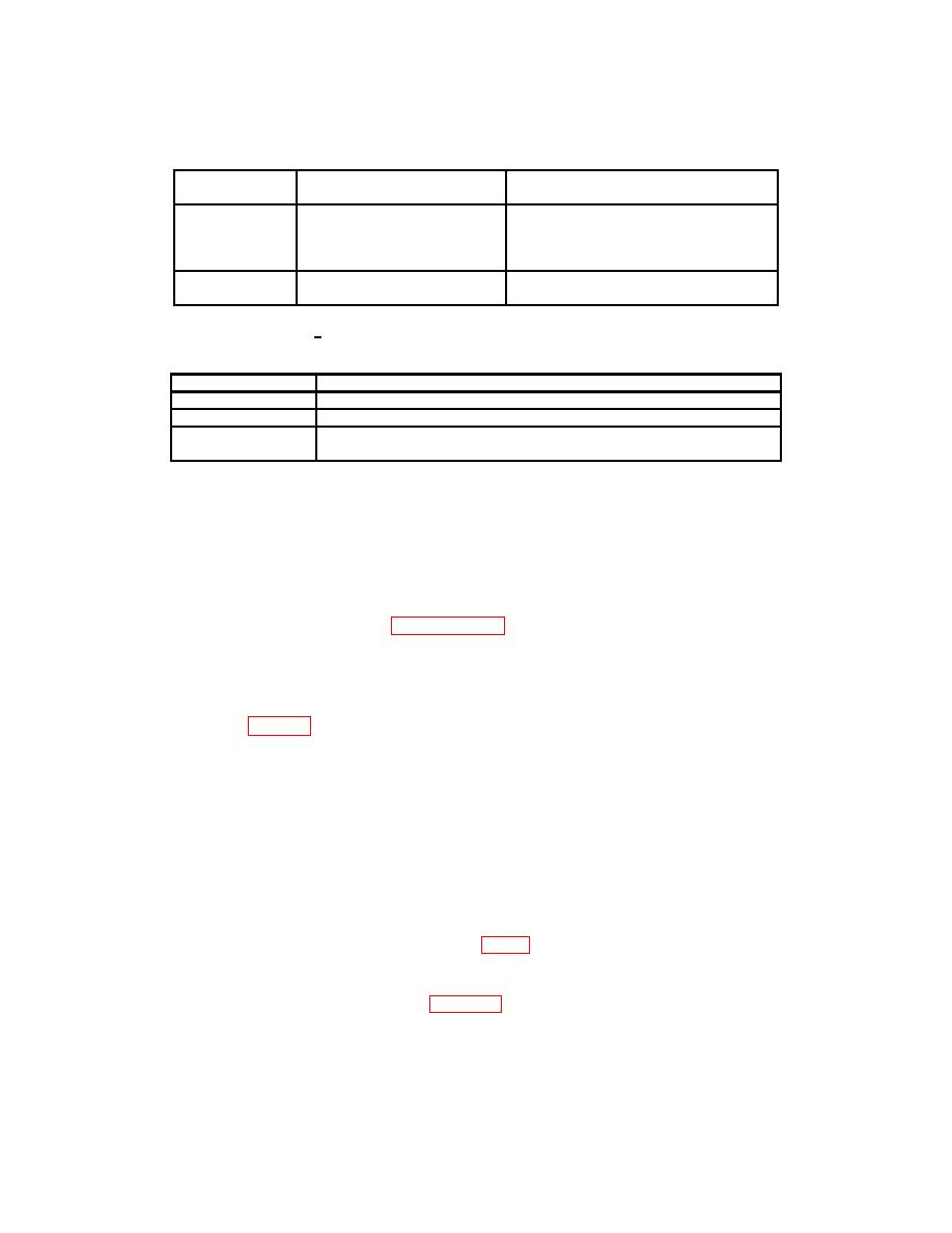
Table 2. Minimum Specifications of Equipment Required
Manufacturer and model
Common name
Minimum use specifications
(part number)
GAGE BLOCK
Range: 0.101 in.
(7900612 and 7901267)
1
0.125 in.
1
0.149 in.
Accuracy:2
SINE PLATE
Range: 5 in.
GGG-B-121 (GGG-B-121)
Accuracy:
2
1Two
required
2Combined
accuracy is +0.00024 in.
Table 3. Accessories Required
Common name
Description (part number)
C CLAMP1
GGG-C-406 (GGG-C-406)
SURFACE PLATE
GGG-P-463B (GGG-P-463B)
STEEL
GGG-P-61 (GGG-P-61)
PARALLEL1
1Two
required. Limited deployed item.
SECTION III
6. Preliminary Instructions
process. Personnel should become familiar with the entire bulletin before beginning the
b. Items of equipment used in this procedure are referenced within the text by common
name as listed in table 2.
c. Unless otherwise specified, verify the results of each test and, whenever the test
requirement is not met, take corrective action before continuing with the calibration.
Adjustments required to calibrate the TI are included in this procedure. Additional
maintenance information is contained in the manufacturer's manual for this TI.
d. Unless otherwise specified, all controls and control settings refer to the TI.
7. Equipment Setup
rear panel.
c. Set TI switches as listed in (1) through (3) below:
3
