
TB 9-4931-535-24
(13) Press keys and enter values using ENTRY keys as listed in (a) through (c) below:
(a) ENTRY dB/DIV to 10 dB.
(b) RBW-VBW-ST ENTRY RES BW to 3 Hz.
(c) ENTRY FREQUENCY SPAN to 100 Hz.
(14) Allow one complete sweep to occur.
(15) Adjust MARKER/CONTINUOUS ENTRY knob to position marker on most
positive point of trace using TI marker amplitude indication.
(16) Press MARKER/CONTINUOUS ENTRY OFFSET key to on and then
MARKER/CONTINUOUS ENTRY ENTER OFFSET key.
NOTE
If TI offset frequency indication is not .0 Hz and amplitude
indication is not .0 dB, press MARKER/CONTINUOUS
ENTRY OFFSET key to off and repeat (16) above.
(17) Adjust MARKER/CONTINUOUS ENTRY knob to move marker down the left
side of trace until TI marker offset amplitude indication is between -59.6 and -60.4 dB.
(18) Press MARKER/CONTINUOUS ENTRY ENTER OFFSET key.
(19) Adjust MARKER/CONTINUOUS ENTRY knob to move marker to the right
side of trace until TI marker offset amplitude indication is between 0.4 and -0.4 dB.
(20) Record TI actual marker offset frequency indication in table 7.
(21) Press keys and enter values using ENTRY keys as listed in (a) through (d) below:
MARKER/CONTINUOUS ENTRY OFFSET to off.
(a)
RBW-VBW-ST ENTRY RES BW to 10 Hz.
(b)
RBW-VBW-ST ENTRY VIDEO BW to 10 Hz.
(c)
ENTRY FREQUENCY SPAN to 200 Hz.
(d)
(22) Repeat (14) through (20) above.
(23) Repeat (21) and (22) above for remaining TI settings listed in table 7.
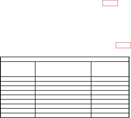
Table 7. 60 dB Bandwidth
Test instrument
ENTRY
Actual marker offset
RBW-VBW-ST
FREQUENCY SPAN
ENTRY RES BW
frequency
settings
indications
settings
3
Hz
100
Hz
10
Hz
200
Hz
30
Hz
500
Hz
100
Hz
2
kHz
300
Hz
5
kHz
1
kHz
20
kHz
3
kHz
50
kHz
10
kHz
100
kHz
30
kHz
500
kHz
15