
TB 9-4935-558-40
Table 2. Minimum Specifications of Equipment Required
Manufacturer and model
Common name
Minimum use specifications
(part number)
(SKD4850-107)
2.1515 .001 in.
P/O SK-A-4850-103
WEIGHT
(8598963)
94 1 lb.
P/O 10-10525
WEIGHT TABLE
(SKA4850-104)
1 .25 lb.
PRELIMINARY OPERATIONS
6. Preliminary Instructions
a. The instructions outlined in paragraphs 6 and 7 are preparatory to the calibration
process. Personnel should become familiar with the entire bulletin before beginning the
calibration.
b. Items of equipment used in this procedure are referenced within the text by common
name as listed in table 2.
c. Unless otherwise specified, verify the result of each test and, whenever the test
requirement is not met, take corrective action before continuing with the calibration.
Adjustments required to calibrate the TI are included in this procedure.
d. Unless otherwise specified, all controls and control settings refer to the TI.
7. Equipment Setup
a. Release any applied load on slide of TI force gage.
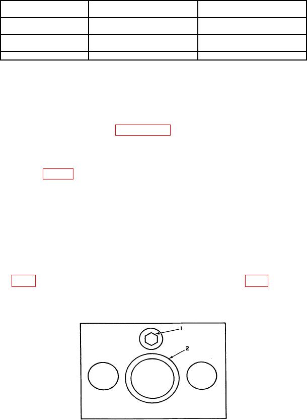
b. Stand the TI in an upright position on the calibration stand. Tighten the adjusting
the pointer on the gage just begins to deflect. Loosen adjusting screw slider until all the
load on the force gage is removed. Tap the slider with finger. The pointer of the force gage
should move with each finger tap if all the load is removed.
1 - Adjusting screw
2 - Slider
Figure 1. Top view test instrument.