
TB 9-5220-212-40
NOTE
Make certain that end stations of perimeter lines tie in with
end stations of diagonals and that end stations of centerlines
tie in with midpoints of perimeter lines as closely as possible.
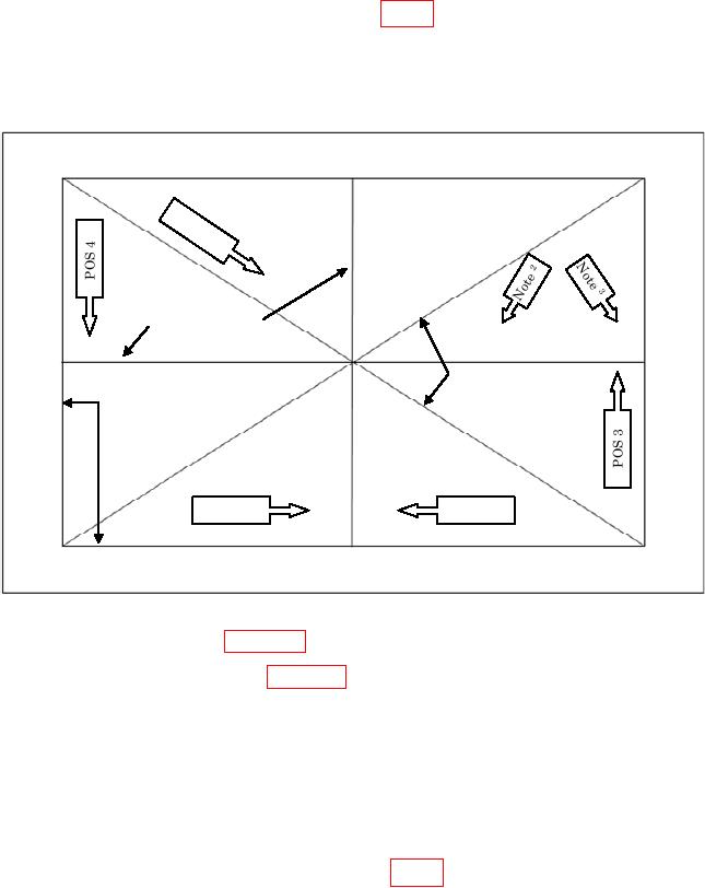
(4) Place autocollimator at position 1 (fig. 1).
NOTE
It may not be possible to position autocollimator exactly as
shown because of size.
NORTH 1
No
te
3
CENTERLINES
EAST
WEST
DIAGONAL LINES
PERIMITER LINES 4
POS 1
POS 2
SOUTH
1 North
will be designated by manufacturer's label.
2 For
small TI surfaces, position autocollimator in POS 2. (This footnote does not apply when using
differential electronic level in Section IV.)
3 Position of autocollimator for small TI's for WEST-EAST CENTERLINE. (This footnote does not apply when
using differential electronic level in Section IV.)
4 The PERIMETER LINES should be a minimum 1 inch in from edge if length of diagonal is 48 inches or less
and 1-1/2 inches in from edge if diagonal is over 48 inches.
Figure 1. Granite Surface Plate - Calibration Setup.
(5) Lay straight edge immediately adjacent to line that is to be calibrated and clamp
to TI.
NOTE
Each line is designated by number
corresponding
to
autocollimator position number (fig. 1).
(6) Mount mirror on carriage and position adjacent to straight edge at first station
to be measured.
5