TB 9-5985-314-35
and adjust RF OUTPUT controls for +6 dBm. Leave TI DEVICE UNDER TEST port
open.
(8) Connect TI as shown in figure 1 equipment setup.
Press receiver system
NOTE
Use 15% SEARCH MODE on receiver system.
(9) Establish a 0.0 dB reference on receiver system.
NOTE
Ensure receiver is in measurement mode.
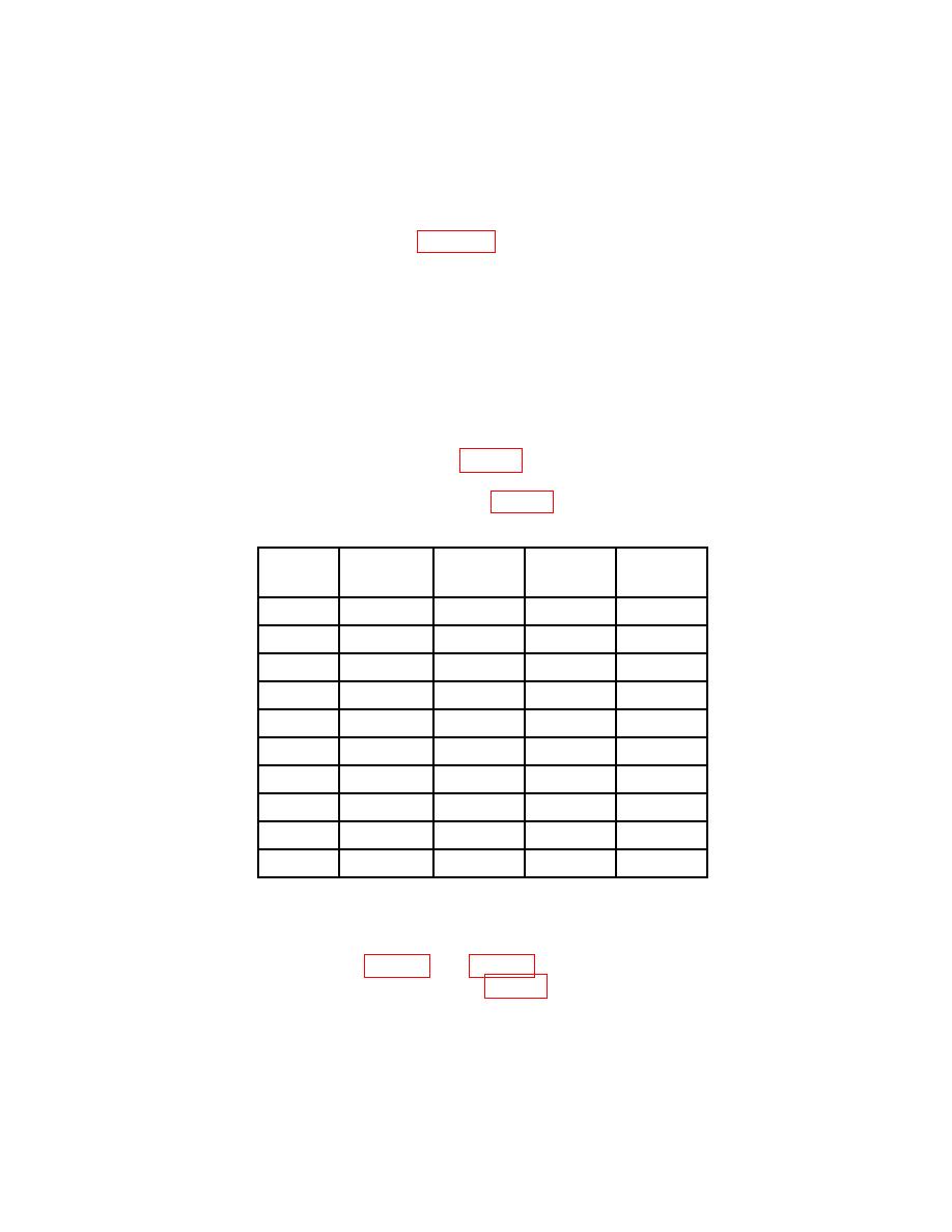
(10) Connect mismatches as listed in table 2 to TI DEVICE UNDER TEST port.
(11) Record receiver system indication in table 4.
Test
Mismatch
Mismatch
Mismatch
Mismatch
2334-001-1
2334-001-2
2334-001-3
2334-001-4
frequency
(12) Repeat technique of (7) through (11) above for remaining test frequencies
recorded in 12 c above.
indication will be within the limits specified in table 2 (for secondary reference as stated in
test report plus or minus specifications of SWR bridges).
b. Adjustments. No adjustments can be made.
17


