
TB 9-6625-086-24
(3) Turn the RANGE switch to NULL.
(4) Adjust the NULL, control for minimum indication on the TI meter.
(5) Repeat (2) through (4) above until the TI meter pointer is within the NULL
region. If the meter pointer does not indicate within the NULL region, perform b below.
NOTE
During calibration, if a 100 ohm thermistor mount is not
available, disregard (6) through (8) below.
(6) Connect the 100 ohm thermistor mount to the TI.
(7) Set the TI MOUNT RES switch to 100 .
(8) Repeat (2) through (5) above.
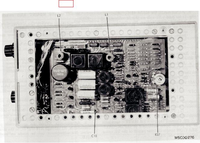
b. Adjustments. Adjust L1 (fig. 1) for null on the TI.
Figure 1. Right interior view.
9. Zero and Vernier
a. Performance Check
(1) Connect multimeter to the TI DVM output (rear panel).
(2) Position the TI RANGE switch to the .01 MW position and adjust the zero
controls for 0.00 volt dc on the multimeter.