
TB 9-6625-1014-24
18. Resistance
a. Performance Check
(1) Certify resistance standard values with leads at 1, 10 and 100 Ω; 1, 10, and
100 kΩ; and 1 MΩ settings respectively using resistance bridge and dc detector (part of
resistance measurement system). Record each value to 100 ppm.
(2) Set RANGE switch to RX0.1Ω and FUNCTION switch to RX1.
(3) Set GEN-DET switch to INT-DC and DET-GAIN control to 2.
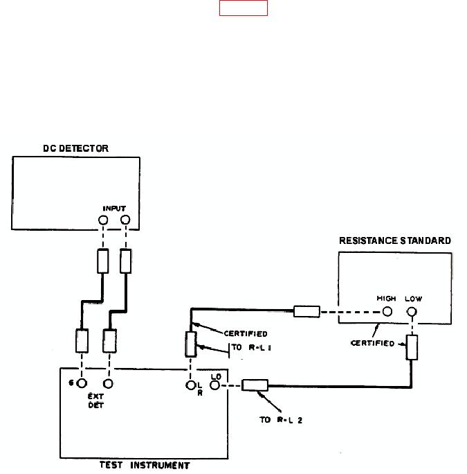
(4) Connect equipment as shown in figure 3.
(5) Adjust resistance standard to 1.00 Ω.
(6) Adjust LRC DIALS until dc detector indicates null.
(7) TI dials will indicate within .1 percent plus one dial division of certified value
recorded in (1) above.
(8) Repeat technique of (5) through (7) above for RANGE switch settings of RX1,
10, 100, 1K, 10K, and 100K, with resistance standard set to 10 and 100 Ω; 1, 10, and 100
kΩ; and 1 MΩ, respectively.
Figure 3. Resistance - equipment setup.