
TB 9-6625-133-40
Table 4. DC Voltage and Linearity Verification.
Nominal
Calibrator
TI
Displayed True Applied
Range
Indication
Min
Measured
Max
(Vdc)
(Vdc)
(Vdc)
(Vdc)
(Vdc)
(ppm)
(ppm)
(ppm)
100 m
------
200 m
-7.9
7.9
100 m
------
20
-74.5
74.5
-100 m 1
------
20
-74.5
74.5
-100 m
------
200 m
-7.9
7.9
12
------
2
-5.2
5.2
1
------
20
-11.5
11.5
-1 1
------
20
-11.5
11.5
-1
------
2
-5.2
5.2
10 3
20
-5.2
5.2
-10
20
-5.2
5.2
19
20
-4.9
4.9
-19
20
-4.9
4.9
100
200
-7.7
7.7
-100
200
-7.7
7.7
1000
1000
-7.7
7.7
-1000
1000
-7.7
7.7
Reverse leads at TI (negative polarity).
1
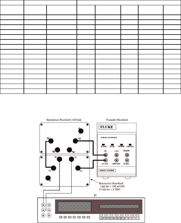
Remove 1 kOhm resistance standard and replace with 10 kOhm resistance standard (positive polarity).
2
3 Remove resistance standards and connect calibrator OUTPUT to TI INPUT. Use calibrator +/- key to
change polarity.
Figure 2. 100 mV dc and 1 V dc Connection.
11