
TB 9-6625-133-40
Figure 1. DCV Input Zero.
(2) Press TI keys as listed in (a) through (i) below.
(a)
CLEAR
(b)
[PWR UP DFLT]
(c)
DCV
(d)
CONFIG
(e)
[FAST] (fast de-selected)
(f)
[RESL] , [7]
(g)
DCV
(h)
INPUT
(i)
[ZERO FUNC] (zero is complete when the BUSY legend goes out).
(3) Populate table 4 True Applied and Calibrator Displayed columns with the values
obtained during DCV characterization (table A-2).
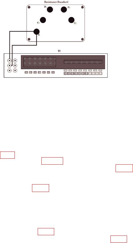
(4) Disconnect shorted leads and connect equipment as shown in figure 2 using 100
kΩ and 1 kΩ resistance standards (divide by 100).
NOTE
Make connections in figure 2 between resistance standards and
transfer standard using short, heavy gage leads/wire.
Resistance of all leads combined to inter-connect resistance
standards and transfer standard should not exceed 10 mΩ
equating to ~1 uV (~0.1 ppm) of loss in this low impedance
path. Lead resistance from resistance standards to TI is not
critical in this high impedance path.
(5) Set TI to the first range in table 4.
(6) Allow measurement to stabilize then record TI indication in table 4.
10