
TB 9-6625-151-40
c. Unless otherwise specified, verify the result of each test and, whenever the test
requirement is not met, take corrective action before continuing with the calibration.
Adjustments required to calibrate the TI are not included in this procedure. Additional
maintenance information is contained in the manufacturer's manual for this TI.
d. Unless otherwise specified, all controls and control settings refer to the TI.
7. Equipment Setup
HIGH VOLTAGE is used or exposed during the performance of
this calibration.
DEATH ON CONTACT may result if
personnel fail to observe safety precautions.
REDUCE
OUTPUT(S) to minimum after each step within the
performance checks where applicable.
a. Ensure TI is not connected to any power source. Remove fuzes M433, M439 if installed.
b. Connect test leads to MULTIMETER INPUT HI and LO. Set MULTIMETER for
resistance measurements.
8. Continuity Tests
a. Performance Check
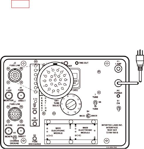
(1) Refer to figure 1 below and set TI switches as listed in (a) through (e) below:
(a) S1 to Off.
(b) S4 to M439.
(c) S6 to 19 Tube.
(d) S5 to Chassis Ground (down).
(e) SW1 Tube Select switch to position 20.
Figure 1. TI Front Panel J2.