
TB 9-6625-1914-24
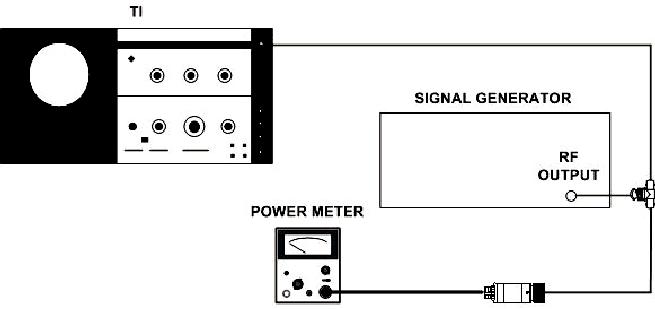
Figure 7. Frequency response (10 to 110 MHz) - equipment setup.
(3) Position IF plug-in switches as listed in (a) through (f) below:
(a) SCAN TIME PER DIVISION to 5 ms.
(b) LOG/LINEAR to LINEAR.
(c) LINEAR SENSITIVITY to 2 mV/DIV.
(d) VIDEO FILTER to OFF.
(e) SCAN MODE to INT.
(f) SCAN TRIGGER to AUTO.
(4) Adjust signal generator frequency to 10 MHz and amplitude for -28.5 dBm.
(5) Adjust TI FREQUENCY control to place 10 MHz input signal on the far left (-5)
graticule line and IF plug-in LINEAR SENSITIVITY (LOG REF LEVEL vernier)
vernier control for a 7 division signal amplitude on display.
(6) Slowly adjust signal generator frequency from 10 to 110 MHz keeping its
amplitude constant by monitoring power meter. Signal pip will remain between 6.6 and
7.4 divisions on display.
26