
TB 9-6625-1914-24
(d) BANDWIDTH switch to 1 kHz.
(e) SCAN WIDTH switch to PER DIVISION.
(f) PER DIVISION switch to 20 kHz.
(g) INPUT LEVEL switch to -20 dBm/dBV.
(h) dBm/dBV switch to dBV.
(i) 20 kHz MARKERS switch depressed.
(2) Position IF plug-in controls as listed in (a) through (g) below:
(a) SCAN TIME PER DIVISION switch to 50 ms.
(b) LOG REF LEVEL switch to -10 dBV.
(c) LOG/LINEAR switch to 10 dB LOG.
(d) VIDEO FILTER switch to OFF.
(e) SCAN MODE switch to INT.
(f) SCAN TRIGGER switch to AUTO.
(g) BASE LINE CLIPPER control fully ccw.
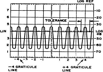
(3) Adjust FREQUENCY and FINE TUNE controls to center a marker on the -4
GRATICULE LINE (fig. 14). Note that a 20 kHz marker appears at about every major
division on display screen.
Figure 14. Scan width accuracy display.
(4) Measure amount of error, in divisions, that marker deviates from +4 graticule
line. Deviation for model 8552B is +0.24 major division and +0.40 major division for
model 8552A (fig. 14).
(5) Position TI switches as listed in (a) through (c) below:
55