
TB 9-6625-1914-24
appear at CENTER FREQUENCY graticule within 3 major divisions for model 8552B
( 5 major divisions for model 8552A).
(4) Set SCAN WIDTH PER DIVISION switch to 500 Hz and RANGE switch to 0-
30 kHz.
(5) Adjust FREQUENCY controls to 0 kHz and adjust ZERO ADJ control to center
local oscillator feed-through on CENTER FREQUENCY graticule.
(6) Adjust FREQUENCY control to center dial marker on CENTER FREQUENCY dial
at 20 kHz. The 20 kHz marker will appear at CENTER FREQUENCY graticule 1 major
division for model 8552B ( 2 major division for model 8552A).
b. Adjustments. No adjustments can be made.
47. Frequency Response
a. Performance Check
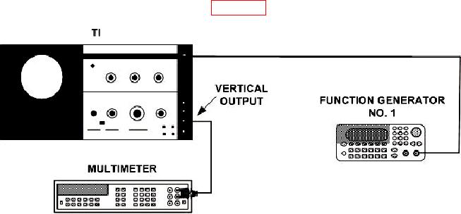
(1) Connect equipment as shown in figure 15.
Figure 15. Frequency response - equipment setup.
(2) Position TI controls as listed in (a) through (g) below:
(a) RANGE switch to 0-30 kHz.
(b) FREQUENCY control to 5 kHz.
(c) FINE TUNE control centered.
(d) BANDWIDTH switch to 300 Hz for model 8552B or 50 Hz for model 8552A.
(e) SCAN WIDTH switch to ZERO.
(f) INPUT LEVEL switch to -40 dBm/dBV.
(g) 20 kHz MARKERS switch out.