
TB 9-6625-1914-24
(6) Carefully adjust amplitudes of function generator no. 2 and signal generator so
that both signal peaks are 3 dB below LOG REF graticule on display screen. The
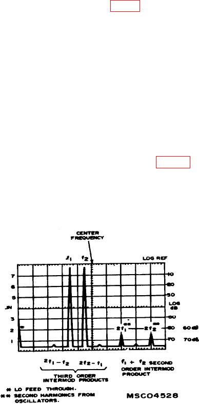
second order intermodulation product (due to analyzer) will occur at 160 kHz (f1 + f2).
Any third order intermodulation products will occur at 50 kHz (2f1-f2) and at 110 kHz
(2f2-f1). The intermodulation products should be below -70 dB graticule line.
(7) Repeat technique of (4) through (6) above with function generator no. 2 at a
frequency of 1.7 kHz and signal generator at a frequency of 2 kHz.
(8) Position SCAN WIDTH PER DIVISION switch to 500 Hz and BANDWIDTH
switch to 30 Hz for model 8552B or 50 Hz for model 8552A. Set SCAN WIDTH to 0-10f.
NOTE
It may be necessary to tune ZERO ADJ control until local
oscillator feed-through is centered at far left graticule line.
(9) Adjust function generator no. 2 and signal generator controls to set both signal
peaks 3 dB below LOG REF graticule on display screen. The signals at 3.4 kHz (2f1)
Any second order
intermodulation product (due to analyzer) will occur at 3.7 kHz (2f1-f2). Any third order
intermodulation product will occur at 1.4 kHz (2f1-f2) and at 2.3 kHz (2f2-f1). All
intermodulation products should be below -60 dB graticule line.
b. Adjustments. No adjustments can be made.
Figure 17. Intermodulation distortion products.
61