
TB 9-6625-1918-24
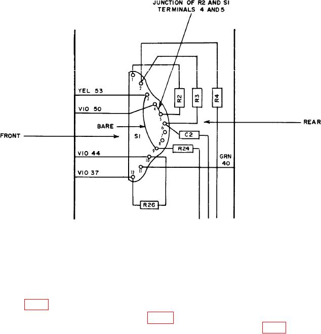
Figure 3. Wattmeters TS-779B/U and Model 451 BOLO RES switch S1 test point location -
right side view
b. Adjustments
(1) Set BOLO BIAS CURRENT (BIAS CURRENT on TS-779/U) switch to OFF.
(2) Rotate ZERO SET COARSE and FINE controls fully cw.
(3) Rotate R8 (fig. 4) fully cw and then one eighth turn ccw.
(4) Connect multimeter to TEST POINT 1 (fig. 2). For TS-779B/U and General
Microwave Model 451, connect multimeter to junction of R2 and S1 terminals 4 and 5 (fig. 3).
(5) Change BOLO BIAS CURRENT (BIAS CURRENT on TS-779B/U) switch
positions until multimeter indicates 2.5 V ac.
(6) Adjust ZERO SET COARSE and FINE controls for a 3.0 V ac indication on
multimeter.
(7) Connect multimeter between bolometer and TI BOLOMETER connector.
7