
TB 9-6625-1935-24
(15) Set RANGE switch to 10 mW and power meter calibrator FUNCTION switch to SET.
(16) Disconnect multimeter from TI RECORDER output connector.
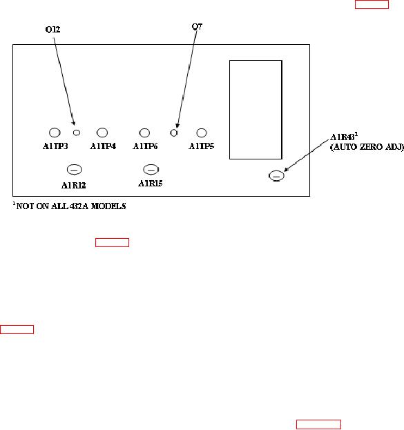
(17) Connect multimeter (differentially) between A1TP5 and A1TP6 (fig. 3).
Figure 3. Test instrument - right side view.
(18) Adjust A1R12 (fig. 3) for multimeter indication of 0.1 mV dc (R).
(19) Set power meter calibrator FUNCTION switch to CHECK. Multimeter will
indicate 0.4 mV dc.
(20) Set power meter calibrator FUNCTION switch to SET.
(21) Connect multimeter (differentially) between A1TP3 and A1TP4 and adjust
A1R15 (fig. 3) for multimeter indication of 0.1 mV dc (R).
(22) Set power meter calibrator FUNCTION switch to CHECK. Multimeter will
indicate 0.4 mV dc.
NOTE
If adjustments were made in (14) through (22) above, repeat b
(1)
through
(13)
above
and,
if
applicable,
set
OPERATE/CALIBRATE
SWITCH
A2S1
to
CALIBRATE. If TI indications in (14) through (22) are within
specified limits, repeat 8 a above.
9. Calibration Factor Test
a. Performance Check
(1) Set power meter calibrator ZERO/TEST switch to TEST and POWER (mW)
switch to 0.1 mW.
(2) Set TI RANGE switch to 0.1 mW (100 μW for model 432B) and
CALIBRATION FACTOR switch to 88%.