
TB 9-6625-1942-24
a. Remove TI from protective cover as required for adjustments.
b. Connect TI to a 115 V ac source.
c. Energize TI and allow at least 30 minutes for warm-up and stabilization.
d. Position TI controls as listed in (1) through (3) below:
(1) FUNCTION switch to DC.
(2) RANGE switch to .1 V.
(3) Connect shorting link between GUARD and LOW INPUT.
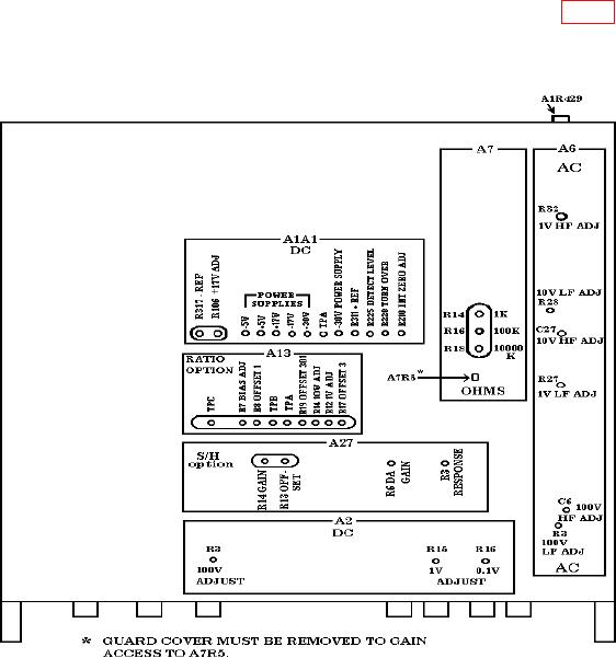
e. Short INPUT terminals. If necessary, adjust A1R429 (rear of TI) (fig. 1) for a 0
0.000002 indication. Remove short.
f. Set RANGE switch to 10 V.
Figure 1. Top interior view - adjustment locations.
5