
TB 9-6625-1947-24
b. Adjustments. Adjust A2R4 (fig. 1) for minimum distortion of at least 46 dB (10 Hz
to 500 kHz) and at least 34 dB (1 to 10 MHz) below fundamental frequency (R).
12. Output Attenuator Accuracy
a. Performance Check
(1) Connect true rms voltmeter to UNBAL output connector, using a 50
feed-
through termination.
(2) Position controls as listed in (a) through (e) below:
(a) FREQUENCY dial to 3.
(b) FREQUENCY RANGE switch to X100K.
(c) OUTPUT LEVEL switch to +10 dBm.
(d) Press IMPEDANCE 50
UNBAL pushbutton.
(e) AMPLITUDE control to +0 dBm.
(3) True rms voltmeter will indicate between +9.85 dBm to +10.15 dBm.
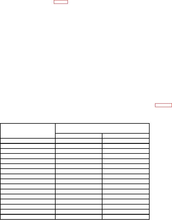
(4) Repeat technique of (2) and (3) above for settings and indications listed in table 7.
True rms voltmeter will indicate within specified limits.
Table 7. Attenuator Accuracy
Test instrument
True rms voltmeter indications
OUTPUT LEVEL
(dBm)
switch settings (dBm)
Min
Max
0
-0.15
+0.15
-10
-9.85
-10.15
-20
-19.85
-20.15
-30
-29.85
-30.15
-40
-39.85
-40.15
-50
-49.85
-50.15
-60
-59.85
-60.15
-1
-0.85
-1.15
-2
-1.85
-2.15
-3
-2.85
-3.15
-4
-3.85
-4.15
-5
-4.85
-5.15
-6
-5.85
-6.15
-7
-6.85
-7.15
-8
-7.85
-8.15
-9
-8.85
-9.15
b. Adjustments. No adjustments can be made.