TB 9-6625-1959-24
(c) Marker, Delta.
(d) FREQUENCY, Center Freq, (harmonic frequency listed in table 3) MHz.
(e) Peak Search.
(5) The spectrum analyzer Mkr will indicate less than or equal to the minimum
limit listed in table 3. If spectrum analyzer is not less than or equal to the minimum limit
listed in table 3, perform b below.
in table 3.
Table 3. Output Buffer Current and Harmonic Suppression
Spectrum analyzer
Test
Instrument
Indication
Frequency Harmonic
(dB)
minimum ( )
(MHz)
frequency Harmonic
100 MHz
200 MHz
2nd
-35
100 MHz
300 MHz
3rd
-40
(7) Adjust OUTPUT AMPLITUDE VOLTS P-P control to 3.0.
(8) Repeat (3) through (6) above.
(9) Adjust OUTPUT AMPLITUDE VOLTS P-P control to 0.5.
(10) Repeat (3) through (6) above.
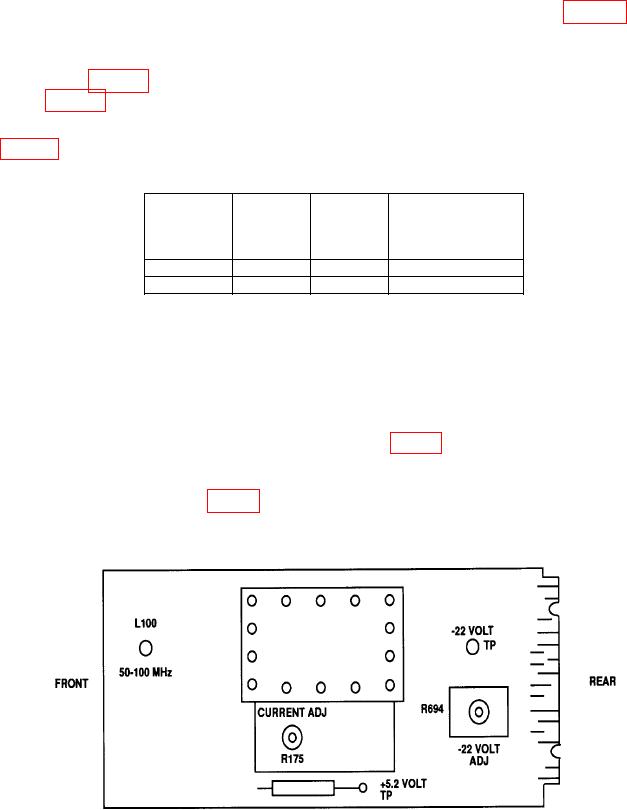
b. Adjustments. Adjust CURRENT ADJ R175 (fig. 2) until third harmonic is at least
40 dB down from reference while assuring that second harmonic amplitude remains 35 dB
down from reference. If second harmonic is equal to or greater than 35 dB down, do not
adjust CURRENT ADJ R175 (fig. 2) to reduce second harmonic at expense of increasing the
third (R).
Figure 2. Main circuit board adjustment locations - right side.
6

