
TB 9-6625-1961-24
8. Amplitude Output and Regulation
a. Performance Check
(1) Connect resistance standard to TI AMPL OUTPUT connector.
(2) Connect multimeter across resistance standard.
(3) Adjust resistance standard to 1 megohm.
(4) Turn AMPLITUDE switch to 100. If multimeter does not indicate between
99.75 and 100.25 V dc, perform b (1) below.
(5) Turn AMPLITUDE switch to 10. If multimeter does not indicate between 9.975
and 10.025 V dc, perform b (2) below.
(6) Record multimeter indication.
(7) Adjust autotransformer for a 105 V output.
(8) Multimeter indication will remain within 4 mV of value recorded in (6) above.
(9) Adjust autotransformer for a 125 V output.
(10) Repeat (8) above.
(11) Adjust autotransformer for a 115 V output.
(12) Repeat technique of (5) above at TI AMPLITUDE switch positions listed in
table 3. Multimeter will indicate within limits specified.
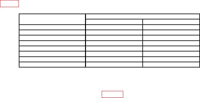
Table 3. Amplitude Output
Test instrument AMPLITUDE
Dc voltmeter indications (V dc)
switch positions (V)
Min
Max
50
49.875
50.125
20
19.95
20.05
5
4.9875
5.0125
2
1.995
2.005
1
0.9975
1.0025
0.5
0.49875
0.50125
0.2
0.1995
0.2005
0.1
0.09975
0.10025
(13) Record multimeter indication on 0.1 volt AMPLITUDE switch position.
(14) Deenergize power module and remove TI.
(15) Connect equipment as shown in figure 2.