
TB 9-6625-1961-24
(4) Measure amplitude of the larger signal. If amplitude of larger signal is not 100
millivolts or less peak-to-peak, perform b (2) below.
(5) Turn PULSE AMPLITUDE control fully clockwise. If amplitude of larger
signal is not at least 1 volt peak-to-peak, perform b (1) and (2) below.
(6) Turn PULSE AMPLITUDE control fully clockwise.
b. Adjustments
(1) Turn PULSE AMPLITUDE control fully counterclockwise.
(2) Adjust R1025 (fig. 1) until amplitude of larger signal is 80 millivolts (R).
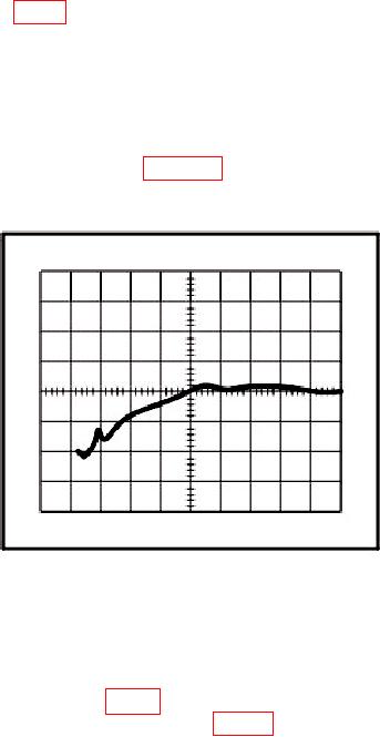
13. Fast Risetime
a. Performance Check
(1) Connect TI positive FAST RISE OUTPUTS to oscilloscope Vertical 1 input.
(2) Adjust oscilloscope controls and TI PULSE AMPLITUDE control as required to
obtain a typical waveform as shown in figure 3. The leading edge aberrations during the
first 10 nanoseconds will be within 2 percent of the peak-to-peak amplitude or 10 millivolts,
whichever is greater. If oscilloscope waveform does not meet requirement, perform b below.
Figure 3. Fast risetime waveform.
(3) Adjust oscilloscope controls and TI PULSE AMPLITUDE control as required to
obtain a waveform of approximately 1 volt peak-to-peak with a sweep time of 500
picoseconds. Measure risetime. If risetime is greater than 1 nanosecond, perform b below.
(4) Repeat (1) through (3) above for TI negative FAST RISE OUTPUTS.
b. Adjustments. Adjust C1000 (fig. 1) for best in-tolerance condition when checking
positive FAST RISE OUTPUTS and C940 (fig. 1) when checking negative FAST
RISE OUTPUTS.