
TB 9-6625-1973-24
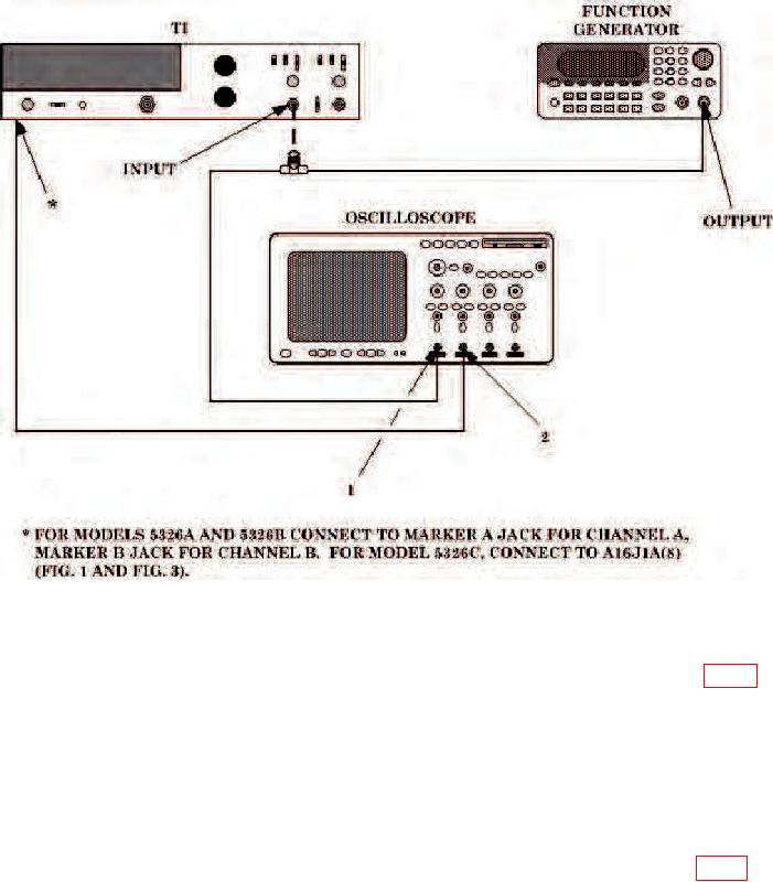
Figure 2. Sensitivity-equipment setup.
(3) Alternately set SLOPE switch to + and - positions while adjusting A2R2 (fig. 1)
until markers displayed on oscilloscope have equal offset about zero volt axis of waveform
for both positions of SLOPE switch (R).
NOTE
Steps (4) through (7) below do not apply to model 5326C.
(4) Increase function generator amplitude to 200 mV rms.
(5) Turn FUNCTION switch to T.I. A to B.
(6) Alternately set SLOPE switch to + and - positions while adjusting A2R24 (fig. 1) to
align markers with zero volt axis of oscilloscope waveform for both positions of SLOPE
switch (R).
NOTE
If calibrating channel A, return FUNCTION switch to FREQ A.
9