
TB 9-6625-1997-24
(a) FUNCTION switch to IF.
(b) IF OUTPUT switch to 1.0 VOLT.
(c) IF MHZ switch to 10.00.
(3) Adjust IF UV control for a 1.0 V indication on IF UV RF SET TO LINE meter.
If measuring receiver does not indicate within the limits shown in first row of table 7,
perform b below.
(4) Repeat technique of (2) and (3) above for switch settings listed in table 7. If
measuring receiver does not indicate within limits specified, perform b below.
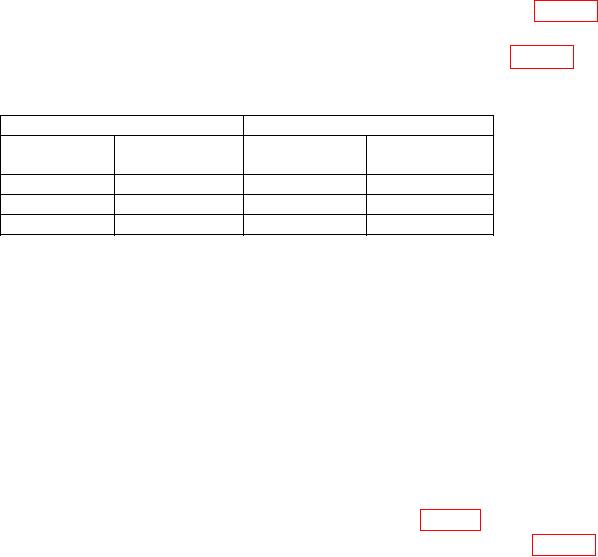
Table 7. IF Output Level Accuracy
Test instrument
Measuring receiver
IF MHZ
IF OUTPUT
switch
switch
Min
Max
10.00
1.0 VOLT
750 mV
1.25 V
100 KUV
75 mV
125
mV
10 KUV
7.5mV
12.5 mV
b.
Adjustments
(1) Adjust IF UV control for a 1.000 V indication on measuring receiver.
(2) Adjust R69 ((IF METER CAL) located on lower right side) for a 1.0 indication on
IF UV RF SET TO LINE meter (R).
12. IF Output Frequency Accuracy
a. Performance Check
output.
(2) Set IF MHZ switch to 4.300 and IF OUTPUT switch to 1.0 VOLT.
(3) Adjust IF UV control for 1.0 indication on IF UV RF SET TO LINE meter.
(4) Repeat technique of (2) and (3) above for switch settings listed in table 8.
Frequency counter will indicate within limits specified.