TB 9-6625-2021-24
NOTE
When the input signal level to the high frequency input
connector exceeds approximately +5 dBm, each digit in the
display becomes a minus sign (-) to indicate overload.
(1) Connect signal generator output to TI N type input.
(Use APC 3.5 male
connector with collar for model 5343A).
(2) Set 10 Hz - 500 MHz/500 MHz - 18 GHz (10 Hz - 500 MHz/500 MHz - 26.5 GHz
for model 5343A) switch to 500 MHz - 18 GHz (500 MHz - 26.5 GHz for model 5343A).
(3) Press FREQ SHIFT (blue) and RESOLUTION 1 Hz pushbuttons.
model 5343A). TI will display a stable indication of applied frequency.
(5) Increment signal generator frequency from 500 MHz to 12.4 GHz. If TI does not
display a stable indication at each frequency increment, perform b below.
model 5343A). TI will display a stable indication of the applied frequency.
(7) Increment signal generator frequency from 12.4 to 18 GHz.
If TI does not
display a stable indication at each frequency increment, perform b below.
b. Adjustments. No adjustments can be made.
20. Power Supply
NOTE
Do not perform power supply check if all other parameters are
within tolerance.
a. Performance Check. Connect multimeter HI to -5.2 V TEST POINT (fig. 3) and
LO to chassis ground. If multimeter does not indicate between -5.1 and -5.25 V dc, perform
b below.
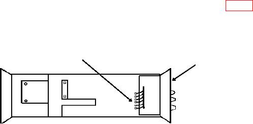
-5 .2 V T E S T P O IN T
FRONT
PANEL
Figure 3. TD-1225A(V)1/U (Hewlett-Packard, Model 5342A/H14), TD-1225A(V)2/U (Hewlett-Packard,
Model
5342A/H16)
and
Hewlett-Packard,
Model
5343A
-
bottom
view.

