
TB 9-6625-2050-24
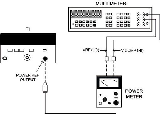
Figure 6. Power reference level - equipment setup.
NOTE
Ensure that multimeter input leads are isolated from chassis
ground when performing (7) below.
(7) Adjust multimeter to measure microvolts and connect positive and negative
input leads, respectively, to VCOMP and VRF connectors on rear panel of power meter.
(8) If multimeter indicates less than 400 microvolts, record indication and proceed
to (9) below. If 400 microvolts or greater, press and hold power meter FINE ZERO switch
and adjust COARSE ZERO control so that multimeter indicates 200 microvolts or less.
Record indication. Release FINE ZERO switch and proceed to (9) below.
(9) Round off indication recorded in (8) above to the nearest microvolt and record
this value as V0.
(10) Set TI POWER REF switch to ON (in) and record multimeter indication as V1.
meter and reconnect to power meter chassis ground. Record multimeter indication as
VCOMP.
formula: