
TB 9-6625-2057-24
Table 3. Frequency Dial Accuracy - Continued
Test instrument
Frequency counter indications
RANGE switch settings
Frequency dial settings
Min
Max
X1K
12
11.64
kHz
12.36
kHz
X10K
1
9.7
kHz
10.3
kHz
X10K
6
38.2
kHz
61.8
kHz
X10K
12
116.4
kHz
123.6
kHz
X100K
1
97
kHz
103
kHz
X100K
6
582
kHz
618
kHz
X100K
12
1.164 MHz
1.236
MHz
b. Adjustments
(1) Set RANGE switch to X1K and frequency dial to 10.
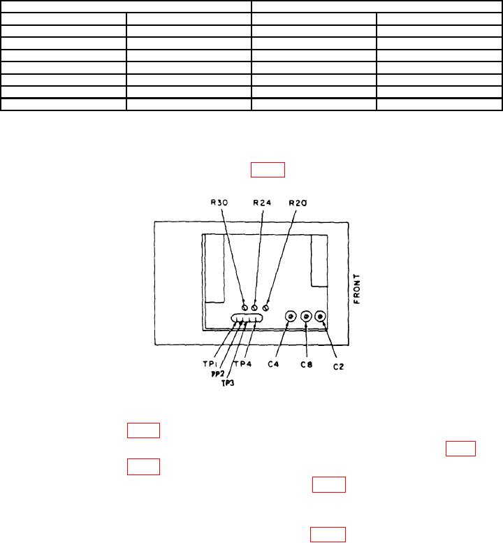
(2) Connect multimeter between TP 4 (fig. 2) and chassis ground.
Figure 2. Test instrument left side view.
(3) Adjust R20 (fig. 2) for 0.0 V dc indication on multimeter (R).
(4) Adjust frequency dial to 1 and connect positive lead of multimeter to TP 1 (fig 2).
(5) Adjust R24 (fig. 2) for a -2.0 V dc indication on multimeter (R).
(6) Set frequency dial to 10 and adjust C2 and C8 (fig. 2) for an indication of 10 kHz
on frequency counter and a -2.0 dc indication on multimeter.
(7) Repeat (4) through (6) above to compensate for interaction.
(8) Set RANGE switch to X100K and adjust C4 (fig. 2) for a 1 MHz indication on
frequency counter.
(9) Set RANGE switch to X5 and adjust frequency dial to 1. Repeat technique of
a (2) through (5) above.
7