
TB 9-6625-2057-24
(4) Set RANGE switch to X1 and FREQ dial to 5.
(5) Repeat a (2) through (5) above.
16. Output Voltage
a. Performance Check
(1) Connect OUTPUT 600
to multimeter using voltage divider.
(2) Position controls as listed in (a) through (c) below:
(a) FREQ dial to 10.
(b) VERNIER to mid position.
(c) RANGE switch to X100.
(3) Adjust AMPLITUDE control fully cw. Multimeter will indicate at least 2.5 V ac.
b. Adjustments. No adjustments can be made.
17. Frequency Response
a. Performance Check
(1) Connect equipment as shown in figure 3, CONNECTION A.
(2) Adjust calibrator to 1.0 V dc and record multimeter indication.
(3) Adjust calibrator to 0.97 V dc and record multimeter indication.
Adjust
calibrator to 1.3 V dc and record multimeter indication.
(4) Connect equipment as shown in figure 3, CONNECTION B.
(5) Set RANGE switch to X100 and FREQ dial to 10.
(6) Adjust AMPLITUDE control until multimeter indication is the same as
recorded in (2) above.
(7) Set RANGE switch and FREQ dial to settings listed in table 7. Multimeter will
be within appropriate values as recorded in (3) above.
NOTE
Do not readjust AMPLITUDE control.
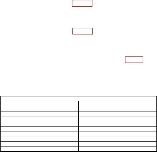
Table 7. Frequency Response
Test Instrument
RANGE switch settings
FREQ dial settings
X1
5
X1
50
X10
50
X10
5
X100
5
X1K
5
X1K
50
X10K
5
561
X10K
1On
models that do not include 56, set FREQ dial to 50.