
TB 9-6625-2066-24
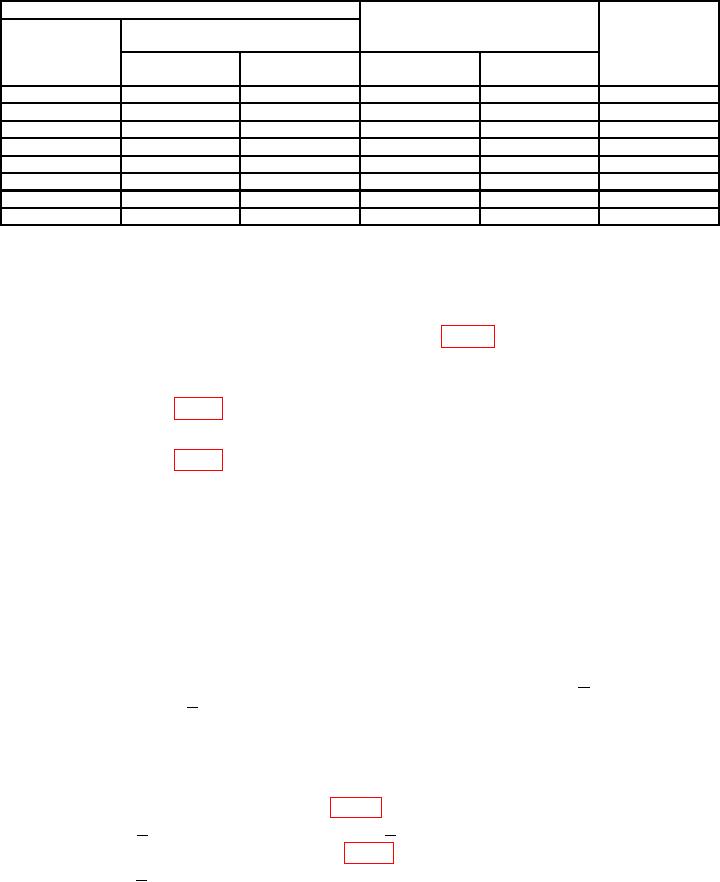
Table 3. Meter Range Accuracy - Continued
Test instrument
Calibrator indication
limits
RANGE
Meter indications
switch settings
0-to-1
0-to-3
Adjustments
(outer scale)
scale
scale
Min
Max
1
.6
---
0.58
0.62
---
1
.4
---
0.38
0.42
---
1
.2
---
0.18
0.22
---
3
---
3
2.94
3.06
---
10
1
---
9.8
10.2
---
b(5) and (6)
30
---
3
29.4
30.6
100
1
---
98.0
102.0
---
300
---
3
294.0
306.0
---
b. Adjustments
(1) Connect the divider to the calibrator output and TI input. Adjust calibrator
output for 1.000 V, 400 Hz.
(2) A d j u s t R 2 9 M E T E R C A L 1 M V R A N G E ( f i g . 1 ) u n t i l T I m e t e r i n d i c a t e s
1 on 0-to-1 scale (R).
(3) Adjust calibrator output for 100 mV, 400 Hz.
(4) Adjust R3 (fig. 2) until TI meter indicates 1 on 0-to-1 scale (R).
(5) Adjust calibrator output for 30 V, 400 Hz.
(6) Adjust R4 (fig. 2) until meter indicates 3 on 0-to-3 scale (R).
9. Frequency Response
a. Performance Check
(1) Connect calibrator wideband to TI input, using calibrator cable and 50
load.
(2) Set TI RANGE VOLTS DB switch to .001.
(3) Adjust calibrator for 1 kHz and output for an indication of 1 on TI meter 0-to-1 scale.
(4) Press calibrator NEW REF pushbutton.
(5) Adjust calibrator frequency between 10 Hz and 2 MHz while maintaining a full
scale indication on TI meter. If calibrator does not indicate between +2% from 10 Hz
to 1 MHz and between +5% from 1 MHz to 2 MHz, perform b(1) and (2) below.
(6) Repeat technique of (2) through (5) above for RANGE VOLTS DB switch
settings of .1 and 3. If an out-of-tolerance condition exists, perform b (3) through (7) below.
b. Adjustments
(1) Adjust C16 CAL 1MV 2MC (fig. 1) and calibrator until calibrator Error =
indicates within +2 percent at 1 MHz and within +5 percent at 2 MHz (R).
(2) Adjust R33 LOOP GAIN ADJ (fig. 1) and calibrator until calibrator Error =
indicates within +2 percent between 300 kHz and 1 MHz (R).