
TB 9-6625-2076-24
b. Adjustments. No further adjustments can be made.
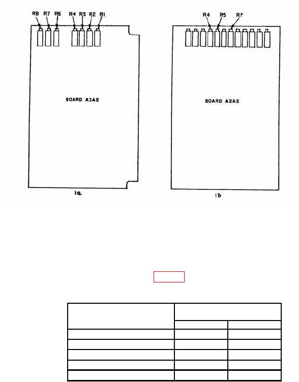
Figure 1. Demodulator/ALC board A3A2 and analog board A2A2.
10. Output Attenuator
a. Performance Check
(1) Enter a frequency of 108.000 MHz into TI. Record exact power meter indication.
(2) Enter RF LEVELS listed in table 6 into TI. The change in power meter
indication from that recorded in (1) above will be within limits specified.
Table 6. Output Attenuator
Test instrument
Power meter difference
RF level
indications (dBm)
Min
Max
-7
0
-2
-8
-1
-3
-10
-3
-5
-14
-7
-9
-20
-13
-15
b. Adjustments. No adjustments can be made.