
TB 9-6625-2076-24
Select Display On and Scaling.
(f)
Set Vertical and Horizontal to Manual.
(g)
Set Vertical Scale to 200mV/ and Horizontal Scale to 500mV/.
(h)
Select Close.
(i)
Set Horizontal Sweep Speed to 10us/.
(j)
Set Channel 1 and Channel 2 to Off.
(k)
(2) Connect TI COMP (rear)
to Channel 2 input of oscilloscope,
and
synthesizer/level generator OUTPUT 50
to Channel 1 input of oscilloscope.
(3) Enter a frequency of 108.000 MHz into TI and press TONE SELECT 9960 FM
only (30 Hz VAR OFF) pushbutton.
(4) Adjust synthesizer/level generator frequency to 9475 Hz and output amplitude
controls to 0 dBm.
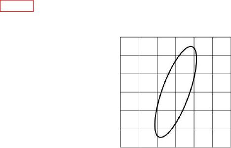
(5) The oscilloscope will display a slowly oscillating circle or ellipse as shown in
(6) Adjust oscilloscope CH1 and CH2 Vertical Scale (volts/division) controls for a
sharply defined display.
Figure 2. Typical FM deviation oscilloscope display (zero beat method).
(7) Slowly adjust synthesizer/level generator frequency to stop rotation of ellipse on
oscilloscope display and record synthesized level generator frequency indication.
NOTE
A slight drift is acceptable.
(8) Adjust synthesizer/level generator frequency to 10,435 Hz and repeat (7) above.
(9) Subtract frequency recorded in (7) above from frequency measured in (8) above
and divide the difference by 2. The quotient will be between 478 and 482 Hz.
b. Adjustments. No adjustments can be made.
9