
TB 9-6625-2083-24
(3) Rotate oscilloscope calibrator knob located below EDIT FIELD pushbutton for
an Err display of 0.0%.
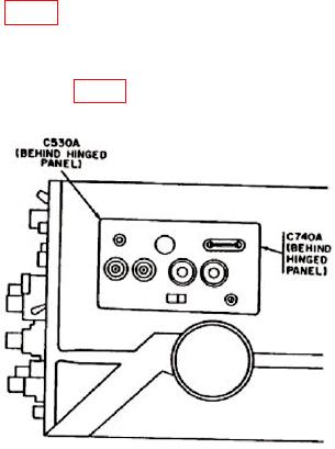
(4) Adjust C740A (fig. 5) to align marker on 10th vertical graticule line.
(5) Rotate oscilloscope calibrator knob located below EDIT FIELD pushbutton for
an Err display of 0.0%.
(6) Adjust C882 and C892 (fig. 4) for 1 marker 2 divisions (R).
Figure 5. Test instrument - right side view.
15. Risetime
a. Performance Check
(1) Position switches as listed in (a) through (d) below:
CH 1 and CH 2 VOLTS/DIV to 20 mV.
(a)
A AND B TIME/DIV AND DELAY TIME to .1 s.
(b)
MAG to X10.
(c)
HORIZ DISPLAY to A.
(d)
(2) Connect oscilloscope calibrator SOURCE/MEASURE CHAN 1 to CH 1
INPUT, using 50 feedthrough termination.
(3) Set oscilloscope calibrator for a CHAN 1, EDGE mode output of 1 s and
amplitude of 100 mV, and rotate oscilloscope calibrator knob located below EDIT FIELD
pushbutton for 5 divisions of vertical deflection on TI.
(4) Measure risetime, using standard risetime technique. Risetime will be 7 ns or less.
(5) Set TI MODE switch to CH 2.
(6) Set oscilloscope calibrator for a CHAN 2, EDGE mode output of 1 s and
amplitude of 100 mV, and rotate oscilloscope calibrator knob located below EDIT FIELD
pushbutton for 5 divisions of vertical deflection on TI.
(7) Measure risetime, using standard risetime technique. Risetime will be 7 ns or less.