
TB 9-6625-2088-24
CAUTION
Observe safety precautions to prevent damage to thermal
converter.
(2) Connect thermal converter to FUNCTION OUT. Monitor output of thermal
converter using multimeter.
(3) Adjust ATTENUATION VERNIER control for a 5 mV reference indication
on multimeter.
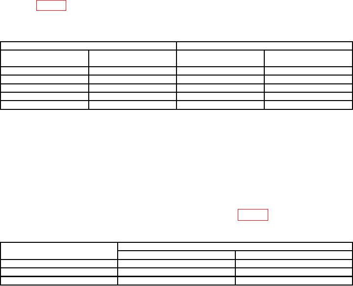
(4) Set FREQ/PERIOD MULTI (Hz/s) switch and frequency dial to positions
listed in table 5. Multimeter will indicate within limits specified.
b. Adjustments. No adjustments can be made.
Table 5. Frequency Response
Test instrument
Multimeter indications (mV)
FREQ/PERIOD MULTI
Frequency dial
(Hz/s) switch settings
settings
Min
Max
1K
.2
4.94
5.06
1K
1.0
4.94
5.06
10 K
2.0
4.94
5.06
100 K
1.0
4.94
5.06
1M
1.0
4.72
5.30
14. Attenuator and Output
a. Performance Check
(1) Set FREQ/PERIOD MULTI (Hz/s) switch to 1 K and frequency dial to 2.0.
(2) Connect true rms voltmeter to FUNCTION OUT using 50
feedthrough termination.
(3) Set ATTENUATION switch to 20/0 and VERNIER control fully cw. True rms
voltmeter will indicate 5.3 V or more.
(4) Adjust VERNIER control for an indication of 5.30 V on true rms voltmeter.
(5) Set ATTENUATION switch to positions listed in table 6. True rms voltmeter
will indicate within limits specified.
Table 6. Attenuation
Test instrument
True rms voltmeter indications
ATTENUATION switch settings
Min
Max
20/40
0.512
V
0.549
V
40/60
49.4
mV
56.8
mV
60/80
4.8
mV
5.9
mV
b. Adjustments. No adjustments can be made.