TB 9-6625-2089-24
(5) Reverse the cable connections at the TI SCOPE TRIG OUT and AUX TRIG OUT.
(6) Adjust oscilloscope controls as required for a pulse display centered on CRT. A
pulse amplitude of 17 to 23 V with a pulse width of 0.5 to 1.5 μs will be displayed on oscilloscope.
(7) Measure risetime and falltime using standard measurement techniques.
Risetime will be less than 0.1 μs and falltime will be less than 0.2 μs.
(8) Set SCOPE TRIG/FREQ MEAS DELAY (μSEC) RANGE switch to OFF.
(9) Connect oscilloscope CH2 input to TPA5 (fig. 1) using X10 probe.
(10) Measure delay between leading edge of signals on oscilloscope CH2 and CH1
inputs. Delay will be between 3.0 and 5.0 μs.
(11) Disconnect probe from TPA5.
(12) Position controls as listed in (a) through (c) below:
(a) SIG GEN FUNCTION switch to SWP 5MHz.
(b) SCOPE TRIG/FREQ MEA DELAY (μSEC) RANGE switch to X4.
(c) SCOPE TRIG/FREQ MEA DELAY (μSEC) MULT control to 1.0.
(13) Connect oscilloscope CH2 input to TPA2 (fig. 1) using X1 probe. Leading edge
of pulse on CH 1 will be 0.5 μs or less from trailing edge of pulse on CH2.
(14) Set AUX TRIG switch to OFF. Pulse on CH1 will disappear. Set AUX TRIG
switch to ON.
(15) Set SIG GEN FUNCTION switch to FIXED FREQ and reverse
MEASUREMENT SCOPE TRIG OUT and AUX TRIG OUT connections on TI.
(16) Adjust SCOPE TRIG/FREQ MEAS DELAY (USEC) MULT control to 1.0 and
SCOPE TRIG/FREQ MEAS DELAY (USEC) RANGE switch to X0.4.
(17) Measure delay between leading edge of signals on oscilloscope CH1 and CH2
inputs. Delay will be between 0.3 and 0.5 μs.
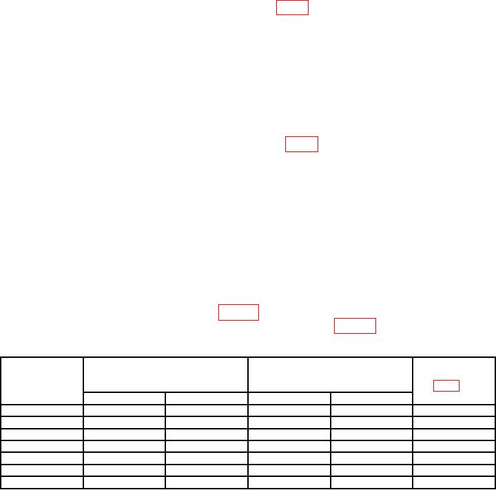
(18) Position controls as listed in table 5. Delay as measured on oscilloscope will be
within limits specified, if not, perform adjustments as listed in table 5.
Table 5. Output Trigger Accuracy
SCOPE TRI/FREQ
Oscilloscope
measurement delay
indications delay
PRF SELECT
Adjustments
(μS)
(USEC)
RANGE
(fig. 1) (R)
Range
Mult
Min
Max
---
---
11.0
4.0
4.8
A2R6
---
X4
---
40
48
A2R5
---
---
1.0
3.6
4.4
A2R27
---
X40
---
36
44
A2R26
X100
---
11.0
400
480
A2R4
---
X400
---
4000
4800
A2R3
---
---
1.0
360
440
A2R25
12

