
TB 9-6625-2089-24
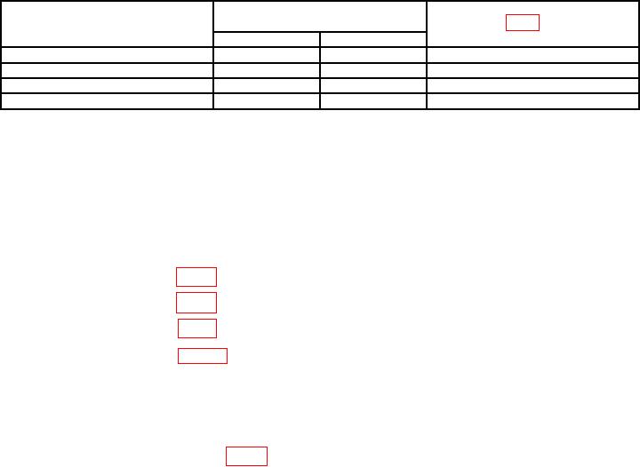
Table 8. Challenge ISLS Spacing Accuracy
Adjustments
Test instrument
Oscilloscope indications
(μS)
CHAL ISLS SPACING
(fig. 1) (R)
(μS)
SELECT
Min
Max
-.15
1.80
1.90
A7R26 for 1.85
+.15
2.10
2.20
A7R28 for 2.15
+.60
2.55
2.65
A7R29 for 2.60
1
>3.02
VARY
<1.0
---
1Adjust
VARY control fully ccw.
2Adjust VARY control fully cw.
(10) Disconnect cable from MAIN RF IN/OUT jack and connect to AUX RF jack. No
pulses will be present on CH1 of oscilloscope.
(11) Set CHAL INHIBIT switch to OFF. Two pulses will be present on CH1
of oscilloscope.
b. Adjustments
(1) Adjust A7R27 (fig. 1) for 2.0 μs (R).
(2) Adjust A7R39 (fig. 1) for .80 μs (R).
(3) Adjust A7R38 (fig. 1) for 0.5 μs (R).
(4) Adjust A7R25 (fig.. 1) for 1.4 μs (R).
13. Suppressor Pulse Accuracy
a. Performance Check
(1) Connect SUPPR OUT to oscilloscope CH1 input using 93 Ω cable. Connect
oscilloscope CH2 input to TPA5 (fig. 1), using X10 probe.
(2) Measure amplitude of pulse on oscilloscope CH1 input. Pulse amplitude will
indicate between 18 and 22 V.
(3) Measure width of pulse on oscilloscope CH1 input. Pulse width will be between
27 and 33 μs at 50 percent if not perform b below.
(4) Measure and note oscilloscope CH1 input pulse time duration between 10 and 90
percent amplitude points for use in (7) below.
(5) Measure and note oscilloscope CH1 input pulse amplitude between 10 and 90
percent points for use in (7) below.
(6) Divide measurement in (5) above by measurement in (4) above to obtain pulse
risetime in V/μs. Pulse risetime will be 20 V/μs or greater.
(7) Measure falltime, using technique in (5) through (6) above. Falltime will be 20
V/μs or greater.
(8) Measure spacing between leading edges of pulses on oscilloscope CH1 and CH2
input. Pulse spacing will be less than 1.0 μs.
(9) Set SUPPR switch to OFF. Pulse on oscilloscope CH1 input will disappear.