
TB 9-6625-2089-24
(5) Measure amplitude of pulse on CH1 input while pressing BIT (MOM)
pushbutton, pulse amplitude will be between 4.5 and 5.5 V.
(6) Measure width of pulse on oscilloscope CH1 input while pressing BIT (MOM)
pushbutton, pulse width will be between 0.4 and 0.6 μs.
b. Adjustments. Adjust A8R14 (fig. 1) until the pulses are within 0.1 μs of each other (R).
16. SIF Reply Marker Accuracy
a. Performance Check
(1) Set controls as listed in paragraph 7 e.
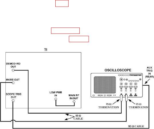
(2) Connect equipment as shown in figure 5.
Figure 5. SIF reply marker - equipment setup.
(3) Four markers will occur on oscilloscope CH2 input starting 2 to 4 μs after second
pulse on CH1 input.
(4) Adjust oscilloscope controls to view second pulse on CH1 input and first pulse on
CH2 input. Vary MKR PHASING control throughout entire range and measure spacing
between second pulse on CH1 input and first pulse on CH2 input. Pulse spacing will vary
from less than 2 μs to more than 4 μs.
(5) Measure pulse amplitude and width of first pulse on oscilloscope CH2 input.
Pulse amplitude will be a minimum of 0.5 V and pulse width will be between 0.10 and 0.20 μs.
(6) Disconnect cable from DEMOD VID OUT and connect 93 Ω cable from TIMING
MKRS OUT to oscilloscope CH1 input. Determine spacing between leading edge of first
and second pulse as listed in (7) through (9) below.
(7) Position oscilloscope controls as listed in (a) through (c) below:
(a) Horizontal controls to view first CH2 pulse on display.