
TB 9-6625-2094-24
(11) Set FREQUENCY VERNIER control to -3 kHz. After 1 minute, record
frequency counter indication. Subtract from indication recorded in (10) above. Difference
will be between 2500 and 3500 Hz.
b. Adjustments
(1) Position TI controls as listed in (a) through (d) below:
FREQUENCY VERNIER control to CAL.
(a)
MODULATION MODE switch to CW.
(b)
OUTPUT step attenuator control for 0 dBm.
(c)
OUTPUT VERNIER control fully cw.
(d)
(2) Set FREQUENCY switches to indicate 500.000 MHz.
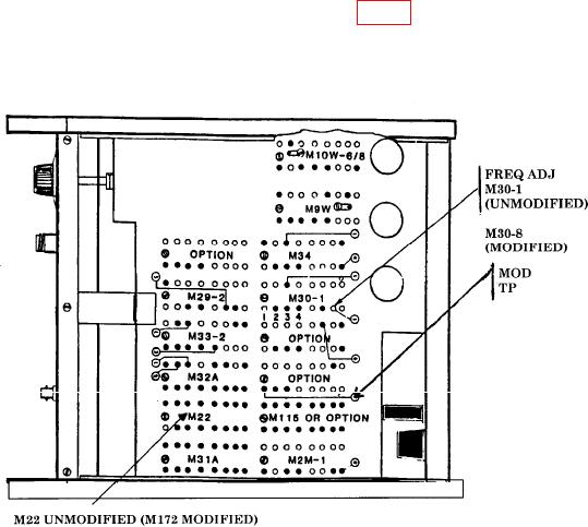
(3) Adjust FREQ ADJ M30-1(UNMODIFIED) (fig. 1) trimmer ccw for minimum
frequency indication on frequency counter, then adjust trimmer cw until frequency counter
indicates 500.000 MHz (R).
Figure 1. Test instrument - bottom view.
7