
TB 9-6625-2099-35
(8) Set DISPLAY MODE switch to CH 2.
(9) Press oscilloscope calibrator CHANNEL pushbutton and press blue soft
pushbutton located below CHAN 2.
(10) Set oscilloscope calibrator VOLTAGE output for 50 mV at 1 kHz amplitude.
(11) Adjust TI time base controls as necessary for a stable display.
(12) Adjust TI CH 2 GAIN control (front panel) for 5 divisions of display.
rotate oscilloscope calibrator knob located below EDIT FIELD pushbutton to obtain
display will indicate within limits specified in table 4; if not, perform b below.
(15) Repeat technique of (11) through (14) above for remaining rows listed in table 4.
Oscilloscope calibrator err display indications will be within limits specified in table 4.
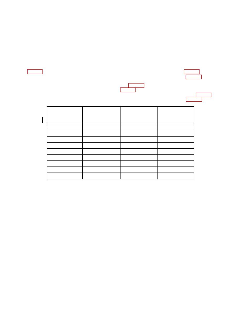
Oscilloscope
calibrator
Test
Oscilloscope calibrator
Test instrument
Voltage
VOLTS/DIV
Err display limits
instrument
output
switch settings
(%)
display divisions
5
mV
20
mV
4
2
20
mV
.1
V
5
2
50
mV
.2
V
4
2
.1
V
.5
V
5
2
.2
V
1
V
5
2
.5
V
2
V
4
2
1
V
5
V
5
2
2
V
10
V
5
2
5
V
20
V
4
2
(16) Deenergize oscilloscope and remove TI from left vertical compartment and
reinstall, using extender.
(17) Energize oscilloscope.
(18) Set CH 1 VOLTS/DIV switch to 5 mV and DISPLAY MODE switch to CH 1.
(19) Ensure oscilloscope calibrator CHAN 1 is connected to CH 1 using a 5-80 pF
standardizer. Press oscilloscope calibrator CHANNEL pushbutton and press blue soft
pushbutton located below CHAN 1.
(20) Set oscilloscope calibrator EDGE output frequency to 1 kHz.
(21) Adjust oscilloscope calibrator output for 6 divisions of display.
CHANGE 1
6
