
TB 9-6625-2102-35
(c) LEVEL.
(d) Enable DC (low-pass filter).
(3) Set FREQ/PERIOD MULT (Hz/s) switch to 10/1K and adjust VARIABLE
control fully cw.
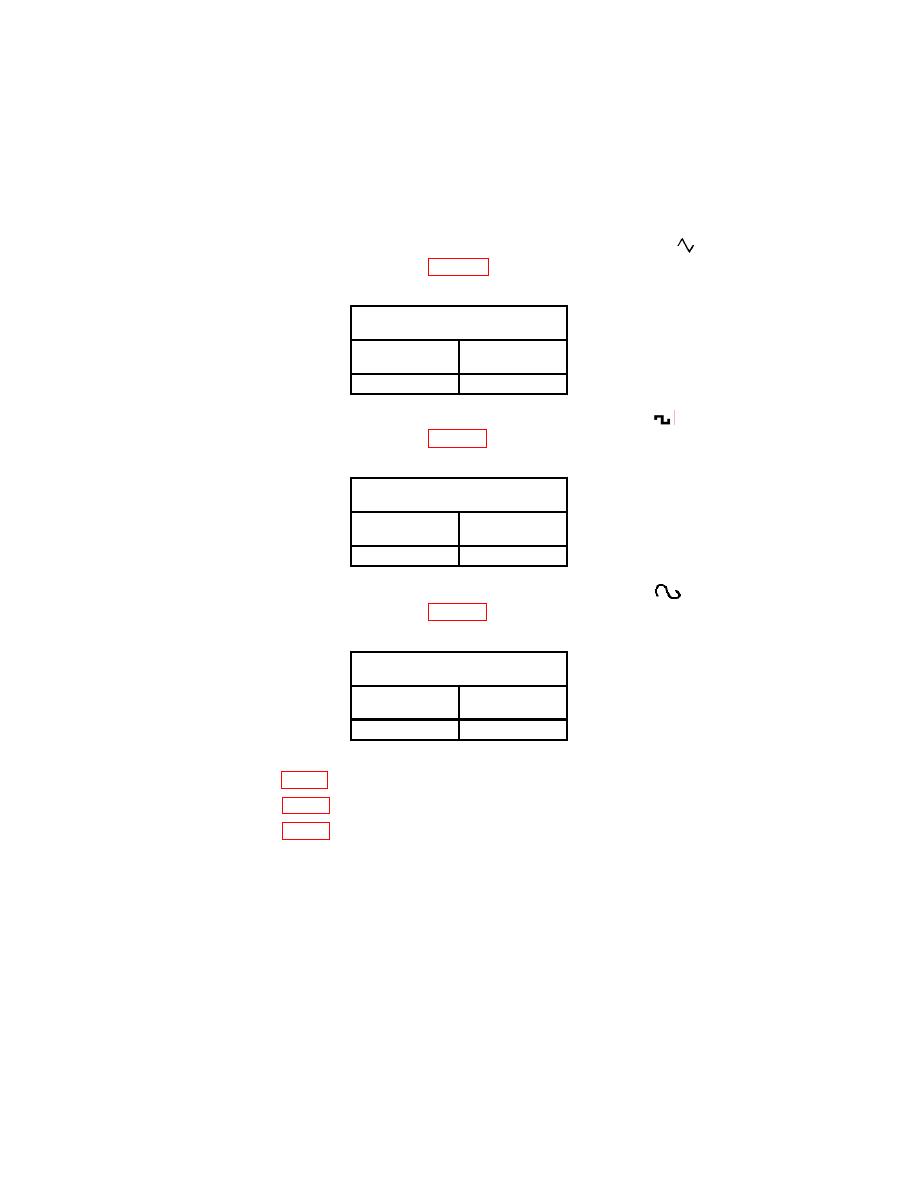
(4) Set TI MODULATION GENERATOR FUNCTION switch to
. If audio
analyzer does not indicate within limits in table 6, perform b (l) below.
Audio analyzer indications
(DC V)
Min
Max
- 0.010
+ 0.010
(5) Set MODULATION GENERATOR FUNCTION switch to
. If audio
analyzer does not indicate within limits in table 7, perform b (2) below.
Audio analyzer indications
(DC V)
Min
Max
- 0.010
+ 0.010
(6) Set MODULATION GENERATOR FUNCTION switch to
. If audio
analyzer does not indicate within limits in table 8, perform b (3) below.
Audio analyzer indications
(DC V)
Min
Max
- 0.010
+ 0.010
b. Adjustments
(1) Adjust R34 (fig. 1) for minimum indication less 10 mV on audio analyzer (R).
(2) Adjust R33 (fig. 1) for minimum indication less 10 mV on audio analyzer (R).
(3) Adjust R76 (fig. 1) for minimum indication less 10 mV on audio analyzer (R).
a. Performance Check
(1) Ensure audio analyzer is connected to MODULATION GENERATOR OUT (600Ω).
(2) Set up audio analyzer to measure distortion.
