
TB 9-6625-2107-24
b. Adjustments. No further adjustments can be made.
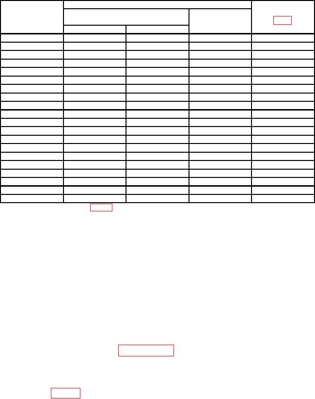
Table 4. Frequency Response
Adjustments/
Test instrument
Calibrator
RANGE
Error display
(VOLTS)
indications
Initial output
( %)
switch settings
(R)
Voltage
0.01
9.0
mV
1.0
MHz
1.0
---
0.01
---
10
Hz
5.0
---
0.0011
0.9
mV
1
kHz
---
---
0.001
---
10
Hz
5.0
---
0.001
---
500
kHz
1.0
---
0.001
---
3
MHz
5.0
---
0.0031
3.0
mV
1.0
kHz
---
---
0.003
---
8.0
MHz
5.0
A3C3 (R)
0.003
---
3.0
MHz
3.0
---
0.003
---
1.0
MHz
1.0
---
0.003
---
10
Hz
5.0
---
11
0.9
V
1.0
kHz
---
---
1
---
3
MHz
3.0
A2C28 (R)
1
---
8.0
MHz
5.0
A3C4 (R)
1
---
1.0
MHz
1.0
---
1
---
10
Hz
5.0
---
31
3.0
V
1.0
kHz
---
---
3
---
500
kHz
1.0
A4C2 (R)
3
---
3.0
MHz
3.0
---
3
---
10
MHz
5.0
---
1Reference
point established in table 3.
10. Final Procedure
a. Deenergize and disconnect all equipment.
b. Annotate and affix DA label/form in accordance with TB 750-25.
CALIBRATION PROCESS FOR
HEWLETT-PACKARD, MODELS 400F AND 400FL
11. Preliminary Instructions
a. The instructions outlined in paragraphs 11 and 12 are preparatory to the calibration
process. Personnel should become familiar with the entire bulletin before beginning the
b. Items of equipment used in this procedure are referenced within the text by common
name as listed in table 2.