
TB 9-6625-2112-24
Table 4. Repetition Rate
Test instrument
Repetition rate
Frequency counter
Repetition rate
vernier control
indications
switch settings
positions
.1 kHz
ccw
10
Hz
or
less
.1 kHz
cw
100
Hz
or
greater
1
kHz
cw
1
kHz or
greater
1
kHz
ccw
100 Hz
or
less
10
kHz
ccw
1 kHz or
less
.1 MHz
ccw
10
kHz or
less
.1 MHz
cw
100
kHz or
greater
1
MHz
cw
1
MHz or
greater
1
MHz
ccw
100
kHz or
less
9. Amplitude
a. Performance Check
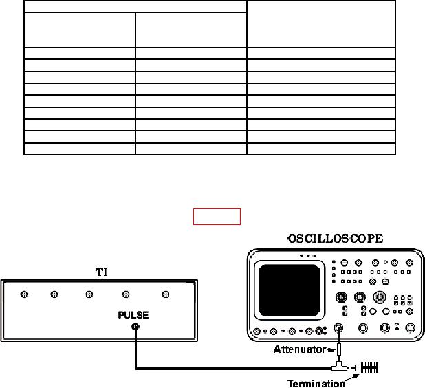
(1) Connect equipment as shown in figure 1.
Figure 1. Amplitude - equipment setup.
(2) Position controls as listed in (a) through (e) below:
(a) REPETITION RATE switch to 10 kHz and vernier fully cw.
(b) WIDTH switch to 10 sec.
(c) AMPLITUDE VERNIER control fully ccw.
(d) AMPLITUDE VOLTS switch to 100 V.
(e) PULSE POLARITY switch to POS.
(3) Adjust oscilloscope controls for a single pulse display.
(4) Adjust AMPLITUDE VERNIER control from minimum to maximum. If pulse
amplitude as indicated on oscilloscope does not vary from 50 V or less to 100 V or more,
perform b below.
(5) Set PULSE POLARITY switch to NEG and repeat technique in (4) above.