
TB 9-6625-2114-24
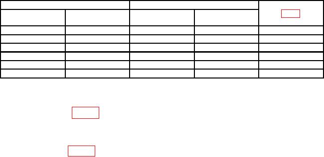
Table 7. Ac Voltage
Test instrument
Calibrator indications (V ac)
Adjustments
RANGE
Indications
switch settings
(V ac)
Min
Max
(R)
1.5 V
1.5
1.4550
1.5450
R5
5V
5
4.850
5.150
R7
R141
15 V
15
14.550
15.450
50 V
50
48.50
51.50
R14
150 V
150
145.50
154.50
R14
500 V
300
285.0
315.0
R14
1Adjust
R14 to provide the best overall compromise for RANGE switch 15 to 500 V ac settings.
b. Adjustments
(1) Adjust R31 (fig. 3) for 0 indication on TI (R).
(2) Fine adjust AC ZERO control for 0 indication on TI.
(3) Adjust calibrator for a 0.5 V indication.
(4) Adjust R3 (fig. 3) for a 0.5 V indication on TI (R).
17. Frequency Response
a. Performance Check
(1) Set RANGE switch to .5V.
(2) Connect AC PROBE tip and ground clip lead together and adjust AC ZERO for
0 indication on TI.
(3) Connect AC PROBE tip and ground clip lead to calibrator OUTPUT HI and LO.
(4) Set calibrator output frequency to 400 Hz and amplitude for a 0.3 V ac indication
on TI.
(5) Press calibrator NEW REF key.
(6) Set calibrator frequency to 20 Hz. Using amplitude output adjustment controls
adjust calibrator amplitude for a 0.3 V ac indication on TI. Calibrator control display Error
will indicate within 10%.
(7) Repeat (6) above at 90 Hz.
(8) Repeat technique of (6) above at 1 kHz, 100 kHz and 1 MHz. Calibrator control
display Error will indicate within 2%.
(9) Adjust calibrator amplitude for a 0.00 ppm control display Error indication. Set
calibrator to STANDBY and disconnect from TI.
NOTE
ZERO
If necessary,
perform
measuring
receiver
and
CALIBRATE.
(10) Connect measuring receiver sensor module input to calibrator OUTPUT HI and LO.
(11) Set calibrator to OPERATE.