TB 9-6625-2127-35
(3) Adjust test oscillator (A3) frequency
11.
Noise Weighting Filters Response
for 1 kHz and output for a 0-dBm indication on TI meter.
Record true rms voltmeter indication.
a.
Performance Check
(4) Adjust test oscillator for frequencies
listed in table 6, keeping true rms voltmeter indication
(1) Set true rms voltmeter (A4) dBm
constant at indication recorded in (3) above. If TI meter
REFERENCE switch to 600 ohms.
does not indicate within limits specified, perform b(1)
(2) Position TI controls as listed in (a)
through (7) below.
through (d) below.
(5) Repeat technique of (3) and (4) above
(a) Press
VF/Nm
600
BAL
for remaining NOISE T\WTG switch positions listed in
pushbutton.
(b) Set INPUT switch to NOISE-
specified, perform adjustments as designated in (a)
BRDG.
through (c) below.
(c) Set NOISE WTG switch to 3 kHz
FLAT.
(d) Set RANGE switch to 0 dBm.
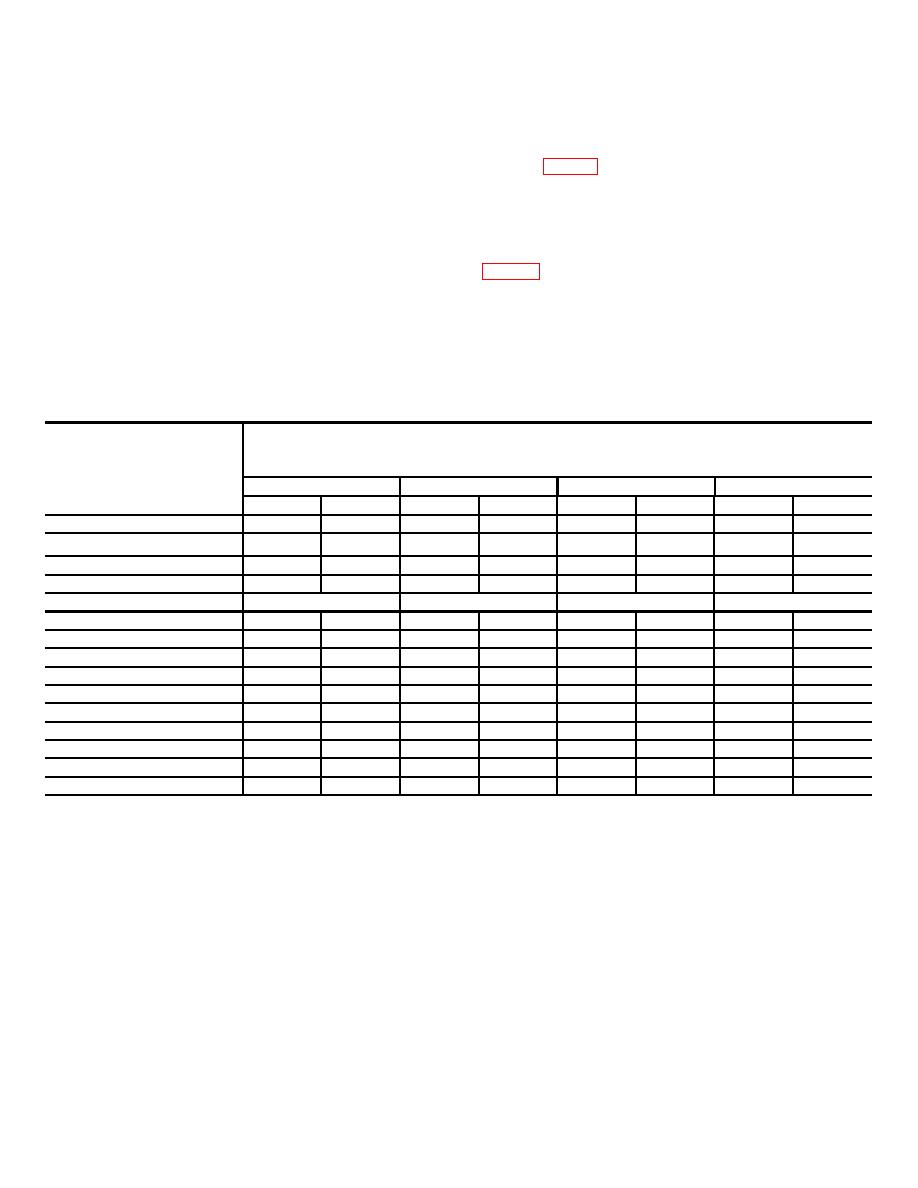
Table 6. Filter Response
Test instrument NOISE WTG switch positions and
Test oscillator
indications
3 kHz FLAT (dBm)
15 kHz FLAT (dBm)
C-MSG (dBm)
PROG (dBm)
Min
Max
Min
Max
Min
Max
Min
Max
1
60 Hz
-1.75
+1.75
-1.75
+1.75
-57.7
-53.7
---
---
200 Hz
---
---
---
---
-27
-23
-19.3 1
-15.3
250 Hz
-1
+1
-1
+1
---
---
---
---
500 Hz
---
---
---
---
-8.5
-6.5
-7.6
-5.6
1 kHz
0 (REF)
0 (REF)
0 (REF)
0 (REF)
2 kHz
-2.25
+1.25
---
---
-2.3
-0.3
+2.8
+6.8
2.5 kHz
-3.5
+0.5
---
---
-2.4
-0.4
---
---
3 kHz
-6
0
---
---
---
---
+4.5
+8.5
4 kHz
---
---
---
---
-17.5
-11.5
+4.5
+8.5
5 kHz
---
---
-1
+1
-31.5
-25.5
+4.5
+8.5
6 kHz
---
---
---
---
---
---
+3.4
+9.4
8 kHz
---
---
---
---
---
---
+1
+7
10 kHz
---
---
-2.25
+1.25
---
---
-12.5
-4.5
12.5 kHz
---
---
-3.5
+0.5
---
---
---
---
15 kHz
---
---
-6.0
0.0
---
---
---
---
1Adjust TI RANGE switch as required for the following checks.
9


