
TB 9-6625-2133-24
c. Unless otherwise specified, verify the result of each test and, whenever the test
requirement is not met, take corrective action before continuing with the calibration.
Additional maintenance information is contained in manufacturer's manual for this TI.
d. Unless otherwise specified, all controls and control settings refer to the TI.
7. Equipment Setup
HIGH VOLTAGE is used or exposed during the performance of
this calibration.
DEATH ON CONTACT may result if
personnel fail to observe safety precautions.
REDUCE
OUTPUT(S) to minimum after each step within the
performance check where applicable.
a. Connect dc power supply to TI XMTR BAT, observing polarity.
b. Connect multimeter to dc power supply.
c. Set FUNCTION switch to OFF.
8. Transmitter Battery Circuit Test
a. Performance Check
(1) Set and hold BAT TEST switch to XMTR position while adjusting dc power
supply for an indication exactly on upper edge of yellow area on TI meter. If multimeter
does not indicate between 11.86 and 12.14 V dc, perform b below.
(2) Release BAT TEST switch and adjust dc power supply output fully ccw.
b. Adjustments
(1) Adjust dc power supply for an indication of 12 V dc on multimeter.
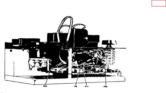
(2) Set and hold BAT TEST switch to XMTR position while adjusting R20 (fig. 1)
for a meter indication at the upper edge of yellow area (R).
Figure 1. Channel alignment indicator - left side view.