
TB 9-6625-2133-24
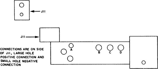
Figure 2. J11 Connection location on receiver alignment test receptacle.
(8) R e p e a t ( 2 ) a b o v e a n d a d j u s t d c p o w e r s u p p l y f o r 1 6 . 5 V i n d i c a t i o n o n
(9) Repeat (7) above. Multimeter will indicate less than 6.4 V dc.
(10) R e p e a t ( 2 ) a b o v e a n d a d j u s t d c p o w e r s u p p l y f o r 1 2 V d c i n d i c a t i o n o n
b. Adjustments. No adjustments can be made.
14. Field Strength Monitor Test
a. Performance Check
(1) Disconnect resistance standard and connect signal generator output to XMTR
ANT socket and chassis ground, using 50 feedthrough.
(2) Set FUNCTION switch to XMTR ANT.
will indicate between left and right ALIGN marks.
(4) Disconnect signal generator setup from TI.
b. Adjustments. No adjustments can be made.
15. Signal Generator Output and Attenuation Test
a. Performance Check
(1) Connect spectrum analyzer to RCVR ANT jack and ground.
(2) Position controls as listed in (a) through (c) below:
(a) FUNCTION switch to RCVR ANT.
(b) FREQUENCY MC dial to 52.
(c) RCVR TEST SIG. fully cw.