
TB 9-6625-2137-24
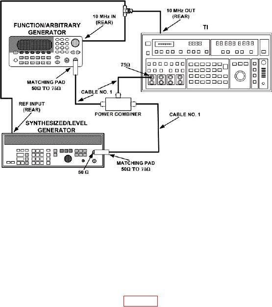
Figure 5. Wideband power accuracy setup.
(7) Set function/arbitrary generator for 200 Hz and synthesizer/level generator
for 1 kHz. Press TI [RDNG OFFSET] pushbutton.
(8) Set synthesizer/level generator to 32 MHz. TI will indicate between 1.8 dBmO.
(9) Set function/arbitrary generator and synthesizer/level generator for -36.3 dBm
and repeat (3) through (8) above.
b. Adjustments. No further adjustments can be made.
18. Phase and Residual Phase Jitter (Option 003 Only)
a. Performance Check
(1) Connect equipment as shown in figure 5.
(2) Set TI ENTRY [RECALL], [0].
(3) Set function/arbitrary generator frequency for 11004 Hz and amplitude for -56 dBm.
to -76 dBm.
(5) Press TI MEASUREMENT ENTRY RANGE [100 dB], and ENTRY, [FREQ],
[1], [0], and [kHz +dB] pushbuttons.
(6) Press TI MEASUREMENT MODE (blue) and [0 JITTER] pushbuttons. TI
phase jitter will be from 10 to 13 degrees p-p.
(7) Disconnect function/arbitrary generator and power combiner from setup.
(8) Connect synthesizer/level generator 75
OUTPUT to TI TERMINATION
input.
75