
TB 9-6625-2139-35
(15) Repeat technique of (12) through (14) above for remaining settings listed in table
(16) Position controls as listed in (a) through (c) below:
(a) HORIZONTAL MODE switch to B.
(b) X10 CAL control to in position.
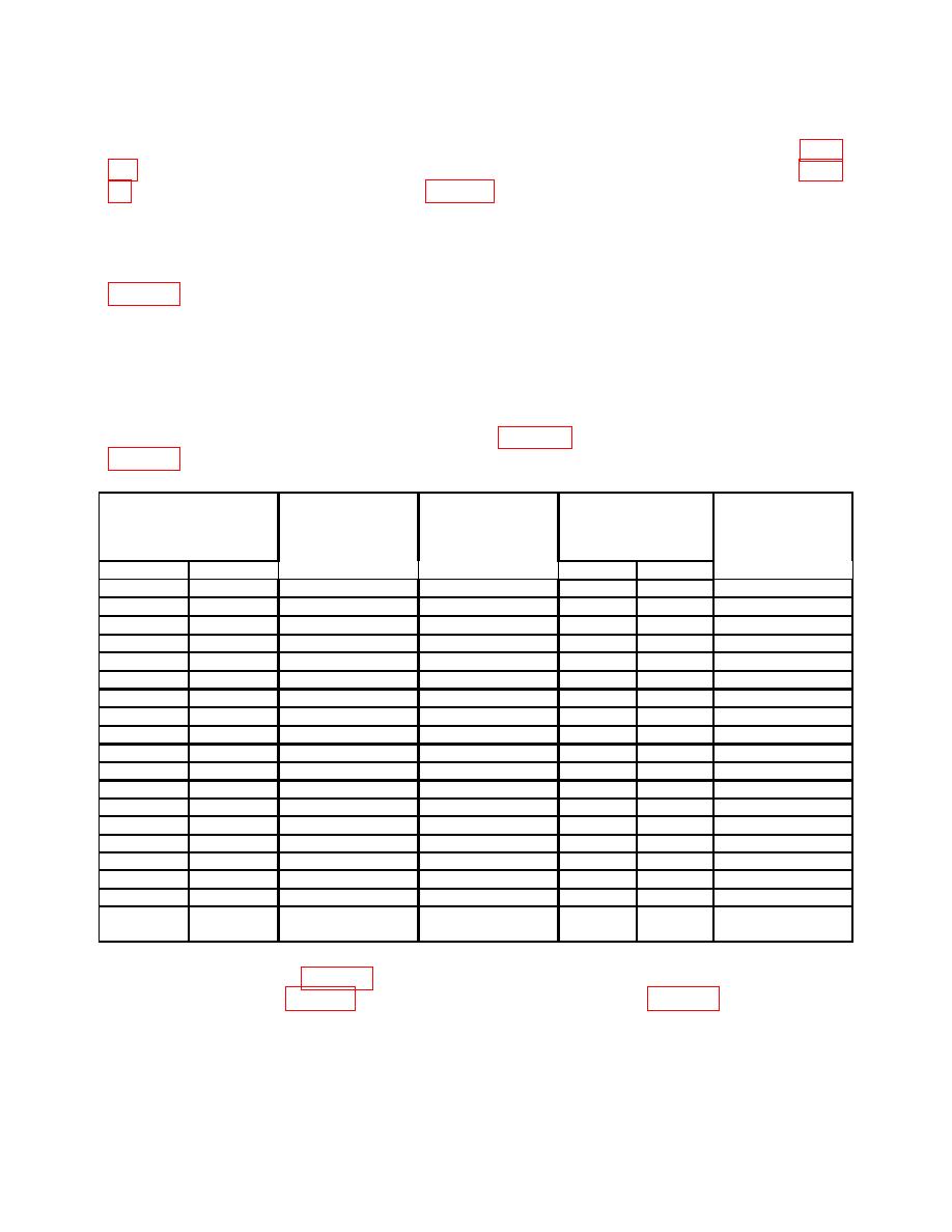
(c) Set TI switch settings and oscilloscope calibrator output to first row listed in
(17) Adjust A and B TRIGGER LEVEL, B INTENSITY, and CH 1 POSITION
controls for suitable viewing.
(18) Adjust horizontal POSITION control to aline 2nd time marker with 2nd vertical
graticule line.
(19) Rotate oscilloscope calibrator knob located below EDIT FIELD pushbutton to
and TI linearity will be within limits listed in table 12, if perform adjustments listed in
Test instrument
linearity
Oscilloscope
Oscilloscope
Test instrument
0.1 division over any
calibrator
calibrator
SEC/DIV
Test instrument
2 center 8 divisions
Err display limits
MARKER
switch settings
%
A
B
output settings
Yes
No
adjustments
.1 s
.05s
b(22) through (24)
50
nS/D
2
.2 s
.1 s
.1 S/D
2
.5 s
.2 s
.2 S/D
2
s
.5 s
.5 S/D
2
1
s
1 s
1 S/D
2
2
s
2 s
2 S/D
2
5
s
5 s
5 S/D
2
10
s
10 s
10 S/D
2
20
s
20 s
20 S/D
2
50
50 s
50 S/D
.1ms
2
.2 ms
.1 ms
.1 mS/D
2
.5 ms
.2 ms
.2 mS/D
2
1
ms
.5 ms
.5 mS/D
2
2
ms
1 ms
1 mS/D
2
5
ms
2 ms
2 mS/D
2
10 ms
5 ms
5 mS/D
2
20 ms
10 ms
10 mS/D
2
50 ms
20 ms
20 mS/D
2
.1 sec
50 ms
50 mS/D
2
A ONLY
(20) Repeat technique of (17) through (19) for remaining TI settings and oscilloscope
output settings listed in table 12. Oscilloscope calibrator err display and TI linearity will be
19
