
TB 9-6625-2139-35
(21) Set X10 CAL control to out position.
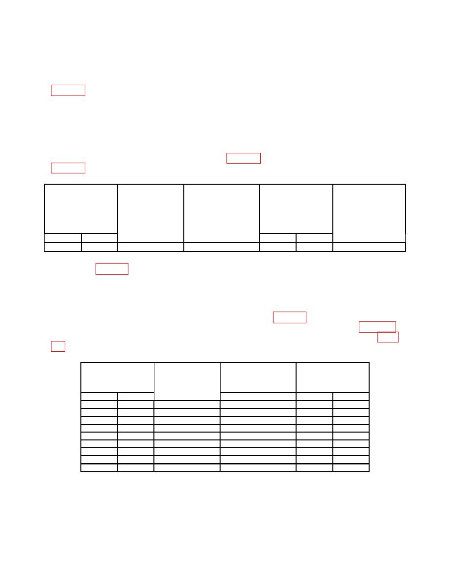
(22) Set TI A AND B SEC/DIV switches and oscilloscope calibrator output as listed in
(23) Adjust A and B TRIGGER LEVEL, B INTENSITY, and CH 1 POSITION
controls for suitable viewing.
(24) Adjust horizontal POSITION control to aline the 1st time marker that is 25 ns
beyond start of sweep with the 2nd vertical graticule line.
(25) Rotate oscilloscope calibrator knob located below EDIT FIELD pushbutton to
and TI linearity will be within limits listed in table 13, if not perform adjustments listed in
Test instrument
linearity
Oscilloscope
Oscilloscope
Test instrument
0.1 division over any
calibrator
calibrator
SEC/DIV
Test instrument
2 center 8 divisions
Err display limits
MARKER
switch settings
%
A
B
output settings
Yes
No
adjustments
.1 s
.05 s
10 nS/D
3
b(25) through (28)
(26) Set A AND B SEV/DIV switches and oscilloscope calibrator output as listed in
first row of table 14.
(27) Adjust horizontal POSITION control to aline the 1st time marker that is 25 ns
beyond start of sweep with the 2nd vertical graticule line.
(28) Rotate oscilloscope calibrator knob located below EDIT FIELD pushbutton to
will indicate and linearity will be within limits specified in table 14.
(29) Repeat technique of (27) and (28) above for settings listed in table 14.
Oscilloscope calibrator err display and linearity will indicate be within limits listed in table
Test instrument
Test instrument
Oscilloscope
Oscilloscope
linearity
SEC/DIV
calibrator
calibrator
0.1 division over any
switch settings
MARKER
Err display limits
2 center 8 divisions
%
A
B
output settings
Yes
No
.2 s
.1 s
10 nS/D
3
.5 s
.2 s
20 nS/D
3
1 s
.5 s
50 nS/D
3
2 s
1 s
.1 S/D
3
5 s
2 s
.2 S/D
3
s
5 s
.5 S/D
10
3
s
s
S/D
20
10
1
3
s
s
S/D
50
20
2
3
s
S/D
.1 ms
50
5
3
20
